Reading...
![]()
Play button
![]()
Play button
![]()
Use LEFT and RIGHT arrow keys to navigate between flashcards;
Use UP and DOWN arrow keys to flip the card;
H to show hint;
A reads text to speech;
31 Cards in this Set
- Front
- Back
- 3rd side (hint)
|
List the four deformity components
|
angulation
rotation translation length |
|
|
|
Explain why a TSF corrects for 6 axis deformity or you need 6 deformity parameters to define a single bone deformity
|
Deformity b/w two bone segments can be characterized by three angles (rotations in x/y/z plane) and three displacements (transplations in x/y/z plane)
|
|
|
|
where is the master tab always located on the TSF and which direction does it face
|
-always on the proximal ring
-always faces anterior -b/w struts 1-2 |
|
|
|
Numbered struts: counterclockwise or clockwise
|
-counterclockwise for the PATIENT
|
|
|
|
where is the anti-master tab
|
-empty distal tab b/w struts 1/2
|
|
|
|
when is the anti master tab a "virtual tab"
|
- in a distal 2/3 ring construct (because there is no ring distal to 1/2 strut)
|
|
|
|
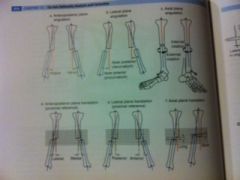
List out the 6 deformity parameters to fully define a clinical deformity
|
1. AP plane angulation (varus/valgus)
2. Lateral plane angulation (recurvatum/procurvatum) 3. Axial plane angulation (int/ext rotation) 4. AP Plane translation (medial/lateral) 5. Lateral Plane translation (Ant/post) 6. Axial Plane translation (long/short) |
Basically:
AP Angulation / Translation Lateral Ang/Trans Axial Ang/Trans |
|
|
what type of TSF construct would you need for correcting a two level deformity
|
3 ring; with 6 struts b/w each pair of rings (12 struts total)
|
|
|
|
to treat a deformity with a TSF; what are three parameters that need to be defined (for computer input)
|
-Frame parameters (struts used, size of rings)
-Deformity parameters -Mounting parameters |
|
|
|
what do deformity parameters define
|
-define the angulation and translations (6 parameters) of the origin on the reference segment and its CP on the corresponding segment
|
|
|
|
list the 6 deformity parameters you need to enter into a TSF program
|
1. AP angulation and translation (varus/valgus and med/lat)
2. Lateral or Sagittal ang/trans (procurvatum/recurvatum and ant/post) 3. Axial ang/trans (rotation and long/short) |
|
|
|
which deformity parameter is measured from radiograph and which is measured from clinical exam
|
- Axial is the only one not measured from radiograph
-can use clinical measurement or CT measurement |
|
|
|
what do mounting parameters define
|
-postion of the CENTER of the reference ring to the assigned origin
|
|
|
|
what info is needed for mounting parameters to be entered into a TSF program (4)
|
1. AP frame offset (frame is med or lateral to origin)
2. Lateral frame offset (ant/post) 3. Axial frame offset (proximal/distal and int/ext rotated) |
|
|
|
when defining axial frame offset for mounting parameters; what points are used
|
rotational offset b/w the master tab (prox reference) or the anti master tab
|
|
|
|
The intent is to place a frame in the neutral position with no offset (mounting parameters). However, if rotational offset isnt accounted (or the frame is offset for better ST clearance) for in the TSF program; what can occur
|
-secondary deformity will be created
-Ex: varus deformity with int rotation offset not accounted for will result in recurvatum deformity bc the frame is corrected for the varus in the oblique plane not an AP plane |
|
|
|
list the modes of correction in TSF
|
1. chronic deformity
2. residual deformity 3. total residual deformity (MC) |
|
|
|
Chronic deformity mode of correction
|
-frame matches the deformity
-frame is then slowly corrected back to a neutral or home position and the deformity should be corrected -"crooked frame on a similarly crooked bone" |
|
|
|
Total residual deformity mode of correction
|
-"crooked frame and a differently crooked frame"
|
|
|
|
placing a ring orthogonal to the proximal bone axis is crucial for Ilizarov frames, is it for TSF
|
-no, but a orthogonal reference rings make planning easier bc you dont have to account for the offset in mounting parameters
|
|
|
|
There are 5 methods of planning;
1. Fracture (Taylor) 2. CORAgin (Paley/Hertzenberg) 3. CORAsponding point (Paley/Hertz) 4. virtual hinge (Standard) 5. LOCA (Taylor) Describe Fracture method |
Fracture method: two corresponding points on opp ends of the fracture (end of a spike and where it fits on the opp fx fragment - origin and CP
-cant be used with congential, developmental or post traumatic residual deformities bc no fx line is visible |
|
|
|
CORAgin method
|
1. the origin is chosen as CORA
2. the CP is determined by using extrinsic data( local length analysis or LLD) -local length analysis is used when desired correction is a pure neutral wedge, the amt of shortening is added to determine the location of the CP |
|
|
|
Local length analysis method
|
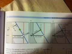
1. measure distance from CORA (the origin) to to convex surface of the deformity (line W)
2. this line is then projected to the moving fragments axis (prox frag) at a 90 degree angle 3. the W line is then translated downt the moving fragments axis until it contacts the original W line, this point is the CP -these deformity parameters can then be entered into TSF program -see pic on next slide |
|
|
|
Extrinsic method of CORAgin (LLD)
|
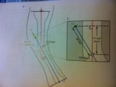
-add the amt of shortening that the pt has to the moving segment axis line (prox seg) in a direction towards the reference fragment
see pic |
|
|
|
describe the CORAsponding point method of planning
|
1. CP is assigned to be at CORA instead of the origin at CORA
2. CP will be on the prox reference line, extending this line to account for a short limb will give the EO or extrinsic origin |
|
|
|
Virtual Hinge Method
|
-Origin and CP are placed at the same location in space creating a virtual axis of correction (or a virtual hinge)
-ideal position of the hinge is at CORA -can be used to create a PURE open wedge osteotomy |
|
|
|
where is the osteotomy located for the LOCA Method of planning (Line of closest approach)
|
-w/ chronic deformities (malunions, etc) CORA on AP view may not correspond to CORA on Lateral view; bc ang and trans are in diff planes
-correcting the deformity at LOCA is the level at which translation b/w fragments is least |
|
|
|
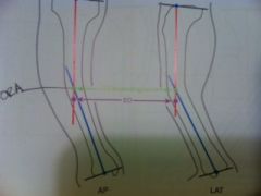
How do you perform the LOCA method of planning
|
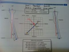
1. assign two levels on the ends of the bone in the AP and lat (same level on both views)
2. determine the translations b/w the reference and deformed fragements at both levels 3. these two values are then plotted on a graph representing the axial plane 4. a perpendicular line is then drawn on the axial graph from ref frag to deformed frag (this line is LOCA and the point it intersects the deformed fragment is LOCA point - also the CP) -osteotomy is chosen at level of LOCA |
|
|
|
when using a distal reference; what frame marker is used for rotational mounting parameters
|
-anti master tab (master tab is used for proximal references)
|
|
|
|
how do you choose which ring to use as a reference ring
|
-the most orthogonal one
-or the juxta articular one |
|
|
|
Define SAR
|
-structure at risk
-can be peroneal nerve or concave side of the bone on a osteotomy |
|