![]()
![]()
![]()
Use LEFT and RIGHT arrow keys to navigate between flashcards;
Use UP and DOWN arrow keys to flip the card;
H to show hint;
A reads text to speech;
10 Cards in this Set
- Front
- Back
- 3rd side (hint)
|
Basic structures of IIR Systems |
1. Direct form(I and II) 2. Cascade form 3. Parallel form 4. Transposed structure 5. All pass structure |
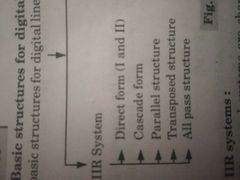
Total 5 forms |
|
|
Basic structure of FIR system |
1. Direct form 2. Cascade form 3. Linear phase filters 4. Frequency sampling |
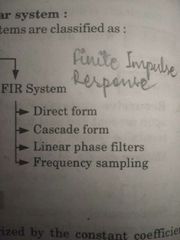
4 forms |
|
|
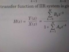
Transfer function of IIR systems |
|
Summation k=0 to M (Bk z^(-k)) / 1 + summation k=1 to N (Ak z^(-k)) |
|
|
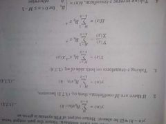
Transfer function of FIR system |
|
Summation k=0 to M-1 (Bk z^(-k)) |
|
|
T/F : FIR filters can be realized recursively and non recursively |
True |
|
|
|
T/F : IIR filters can be realized non-recursively. |
False. IIR filters can be realized only recursively |
|
|
|
For linear phase FIR filter, signal falling entirely in the passband will be reproduced with the delay equal to the _____ of the phase curve. |
signal falling entirely in the passband will be reproduced with the delay equal to the "Slope" of the phase curve. (In which phase?) |
|
|
|
Canonical form of representation |
if the order of difference equations is equal to the number of elements in the block diagram - CANONICAL FORM |
|
|
|
Non-Canonical structure |
If the number of block elements is not equal to the order of difference equations - NON CANONICAL FORM |
|
|
|
Advantages of block diagram representation of digital filter |
- Computational algorithm can be easily written. - memory requirement can be determined easily - block diagram can be determined by a transfer function - relationship between input and output can be determined easily |
|