Reading...
![]()
Play button
![]()
Play button
![]()
Use LEFT and RIGHT arrow keys to navigate between flashcards;
Use UP and DOWN arrow keys to flip the card;
H to show hint;
A reads text to speech;
37 Cards in this Set
- Front
- Back
- 3rd side (hint)
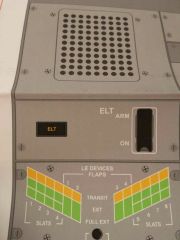
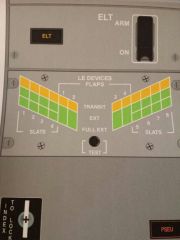
ELT
|
ELT: illuminated, ELT HAS BEEN ACTIVATED and is transmitting on 121.5 243.0 and 406.0
Arm: ELT transmits automatically when it reaches its preset g load limit On: manually activates the ELT |
|
|
|
Leading Edge Devices position indicator
Transit (amber): LE DEVICE IN TRANSIT EXT: related LE SLAT IN EXT FULL EXT: RELATED LE FLAP OR SLAT IN FULL EXT POSITION Test: tests all annunciator panel lights |
|
|
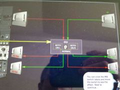
How does IRU provide pitch and roll information to FCCs?
|
If IRS SWITCH is not in normal position, do not use the autopilot, you will not have hardover protection.
|
|
|
|
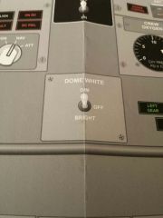
Dome light control
Sets dome light to dim, bright, or off |
|
|
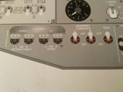
Landing runway turnoff and taxi lights
|
turns on or off exterior lights
retracts and extends retractable landing lights. no speed limitation on retractable landing lights |
|
|
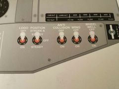
Exterior lights
|
Steady: red and green pos lights, white TE lights illuminate
Strobe and steady: adds the wing tip and tail strobes. |
|
|
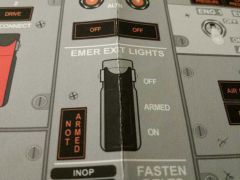
Emer exit lights
|
Switch
OFF: prevents system operation if airplane electrical power turned off or fails armed: emer lights illuminate automatically if DC BUS 1 fails or AC power is turned off. ON: emer lights on NOT ARMED : SWITCH NOT IN ARMED POSITION |
|
|
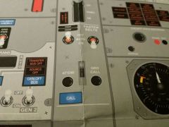
Fasten seatbelts, CALL LIGHT, ATTEND/ GRD CALL
|
Fasten Seatbelts auto: illuminated automatically when gear or flaps extended, extinguished when GEAR is retracted.
ground call: sounds a horn in nose wheel well until released. ATTEND: sounds two tone chime in cabin, illuminates both pink master call lights |
|
|
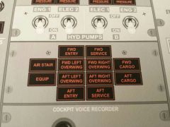
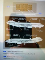
Exterior door annunciator lights
|
illuminated: associated door is not closed and locked
equip: refers to TWO access doors: nose compartment door and E and E bay door. |
|
|
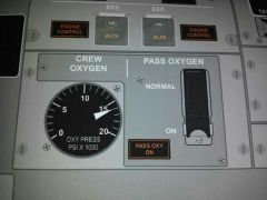
Oxygen panel
|
Crew oxygen: indicates pressure at crew O2 cylinder (1850psi is full)
Pass Oxygen Normal: masks drop if cabin alt climbs to 14,000 ON: activates system and drops masks PASS OXY ON: pax O2 system is operating and masks have dropped |
|
|
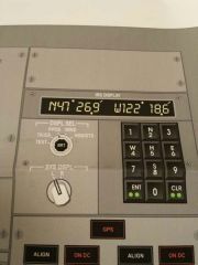
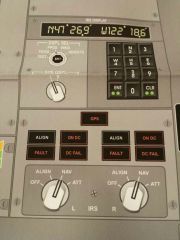
IRS display unit
|
Display selector:
Test: all lights in data display and mode selector unit illuminate, followed by a 10 sec test, use only during alignment TK/GS: true track/groundspeed ppos: lat/lon wind: true wind dir/ wind speed HDG/STS: true hdg, during ALIGN , TIME REMAINING IN MIN TO ALIGN COMPLETE SYS DSPL: R or L: SELECTS LEFT or RIGHT IRS for data display |
|
|
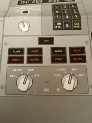
IRS MODE SELECTOR UNIT
|
GPS:
ILLUMINATED, FAILURE OF BOTH GPS UNITS, ON recall: failure of a single gps unit ALIGN: ILLUMINATED steady: IRS operating in ALIGN, ATT mode, or shutdown cycle flashing: ALIGN not complete due to 1. no position entry 2. significant difference between previous and entered positions (VERIFY POSITION message) 3. Unreasonable position entered -loss of ac or dc power -IRU fault condition -aircraft was moved during alignment process (IRS MOTION messgae on FMC) ALIGN: EXTINGUISHED a. IRS not in align mode b. ALIGN COMPLETE c. Mode sel in ATT, att info avail, hdg info avail if mag hdg entered FAULT: system fault affecting related IRS ATT OR NAV modes detected IRU CAN LOSE ALIGNMENT IF: -mode selector moved to OFF, ALIGN, or NAV -LOSS of ac or dc power -fault in the IRU if you see the fault light, select hdg/sts and system will display a fault code. ON DC Light related IRS operating on DC power from switched hot battery bus. AC power not normal on ground, horn will sound in wheel well momentarily illuminates during alignment self test DC FAIL light DC power for the related IRS is not normal, other lights extinguished: IRS operating normally on AC power IRS Mode selector OFF : ALIGNMENT IS LOST, power removed from the system after 30 sec shutdown cycle ALIGN: initiates the alignment cycle, also updates alignment by going from NAV to ALIGN NAV: system enters NAV mode after completion of ALIGN cycle, IRS info avail to airplane systems ATT: provides only attitude and heading info Power Source IRS 1: AC STANDBY (PRIMARY), Switched Hot Battery Bus (Backup) IRS 2: #2 AC Transfer bus (primary), Switched Hot Battery Bus (backup) If loss of ac power and transfer to dc power, IRS 1 will operate off if its normal source, the AC Standby Bus through the inverter. IRS 2 will operate off switched hot battery bus for 5 minutes then shut down. ON DC LIGHT will illuminate on right side only. On ground, horn will sound to alert ground personnel of battery drain. IRS MUST BE TURNED OFF BEFORE REMOVING AC POWER, WHEN POWERING DOWN THE AIRPLANE. |
|
|
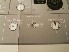
Engine Start Switches
|
GND:
opens start valve, closes eng bleed valve for ground starts, arms selected igniters to provide ignition when eng start lever is moved to IDLE for flight: arms both igniters.. AUTO: (option) ignition normally off, igniters activated if uncommanded rapid decrease in N2 occurs OFF: ignition normally OFF, but both igniters activated when start lever in IDLE and uncommanded rapid decrease in N2 occurs CONT: provides ignition to selected igniters when engine operating and start lever in IDLE, (in flight, provided to both igniters if N2 below idle) FLT: provides ignition to both igniters when engine start lever is in IDLE IGNITION SELECT SWITCH : IGN L: L igniter for both eng IGN R: R igniter for both eng BOTH: both igniters for both eng power source Left Igniter: respective AC Transfer Bus Right Igniter: AC Standby bus |
|
|
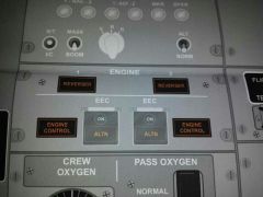
ENGINE PANEL
|
REVERSER:
Illuminated during normal operations when reverser is commanded to stow (10 seconds). If longer than 12 seconds, MC and Engine annunciator light) a. isolation valve or thrust reverser control valve not in commanded position b. reverser sleeve not in commanded state c. auto restow activated, reverser held in the stow position hydraulically ( will operate normally on landing) d. failure of synchronization shaft lock circuitry ENGINE CONTROL: Illuminated if EEC is not dispatchable due to faults in sys illuminates if on ground, below 80kts or 30 sec after touchdown EEC: SWITCHES ON: normal mode selected ALTN: EEC HAS SWITCHED TO ALTN control mode or selected manually ON and ALTN: operating in SOFT ALTN MODE. In SOFT ALTN MODE, at idle thrust the EEC will switch automatically to hard alternate mode. ALTN: ILLUMINATED ALONE IN HARD ALT MODE. |
|
|
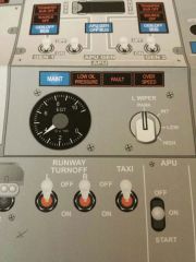
APU panel
|
MAINT: maint should be notified, APU may be operated
LOW OIL PRESSURE: a. during start until oil pressure normal b. auto shutdown due to low oil pressure c. APU switch to OFF, light goes out after 5 min d. disarmed when APU switch in OFF FAULT : a. malfunction exists causing auto shutdown b. APU switch to OFF, light goes out after 5 min b. disarmed in OFF pos OVERSPEED: a. APU rpm exceeded, auto shutdown b. failed self test during normal APU Shutdown c. APU switch to OFF, light goes out after 5 min APU lights are inhibited when APU switch is off for 5 minutes. What will cause an auto shutdown of the APU? -FIRE -Low oil pressure -high oil temperature -overspeed -fuel control unit fail -high EGT -ECU fault |
|
|
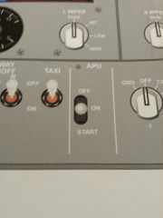
APU START SWITCH
|
OFF: normal position when APU not running
a. WHEN APU RUNNING : trips APU gen off busses, closes APU bleed valve, APU RUNS FOR 60 SEC COOLDOWN PERIOD ON: normal position when APU running on start, opens the apu fuel shutoff valve, arms the apu indicating lights START: INITIATES START SEQUENCE with AC power available uses power from AC Transfer 1. with only DC power available, uses power from the battery (converted to AC through an inverter) |
|
|
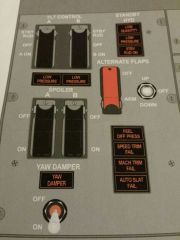
Flight Control Panel
|
FLT CONTROL A B SWITCHES :
STBY RUD: 1. closes associated flight control shutoff valve. 2. Activates standby hydraulic system pump, 3. arms stby hyd low pressure light 3. opens stby rudder shut off valve to pressurize standby rudder PCU. 4. If stby rud sov opens, it extinguishes the associated flight control low pressure light. 5. system B switch to stby rud will trip yaw damp switch to OFF. with *both switches in STBY RUD, you can reselect yaw damp switch to ON to activate STBY YAW DAMP (Wheel to rudder interconnect system WTRIS, aids in turn coordination) OFF: Closes flight control shutoff valve isolating ailerons, elevators, and rudder from associated hyd system. (used by mx only) ON: normal guarded position LOW PRESSURE lights: indicates low hydraulic pressure to ailerons, rudder, and elevators from associated system *deactivated when assoc. flight control switch is in STBY RUD, unless standby rudder shutoff valve fails to open SPOILER A B Switches ON: normal guarded pos. OFF: closes the respective FLIGHT SPOILER shutoff valve. (does not control ground spoilers) *used by mx only YAW DAMPER light: illuminated, yaw damper not engaged. YAW DAMPER SWITCH: OFF: Disengages the yaw damper ON: Engages YD if B flight control switch is in ON pos. engages stby YD if BOTH A and B FLT CONTROL switches are in STBY RUD STBY HYD lights: LOW QTY: ALWAYS ARMED, illuminates if low qty in stby hyd reservoir (<50%) LOW PRESSURE: ARMED ONLY when stby pump is armed or operating, indicates output pressure of stby pump is low STBY RUD ON: indicates stby rud control system is commanded to pressurize stby rud PCU (illuminates automatically when FFM activated, or with loss of A or B system on ground with flaps extended and wheel speed above 60kts, or loss of system A or B in flight with flaps extended.) ALTERNATE FLAPS master switch: OFF: Normal pos ARM: Closes TE flap bypass valve, activates stby pump, arms Stby low pressure light, and arms ALTERNATE FLAPS pos switch ALTERNATIVE FLAPS position switch: only works if ALT FLAPS MASTER IS ARMED. UP: retracts TE FLAPS only. LE devices can not be retracted. switch magnetically held in up position. OFF: Normal pos. DOWN : momentary: LE devices fully extend. alt flaps extension time to flaps 15 is appx 2 minutes. hold: TE FLAPS extend until released *no skew or asymmetry protection. FEEL DIFF PRESSURE : illuminated indicates excessive differential pressure in the elevator feel computer. armed when TE FLAPS are down can be caused by erroneous activation of Elevator Feel Shift Module (Elevator feel computer provides simulated aerodynamic forces using airspeed from the elevator pitot system and stabilizer position, feel is transmitted to control columns by elevator feel and centering unit. If either hydraulic system or elevator feel pitot system fails, excessive hydraulic pressure is sensed by the elevator feel computer and the FEEL DIFF PRESS light illuminates) SPEED TRIM FAIL: illuminated indicates failure of speed trim system. If MC recall extinguished , single channel failure of FCC. (Speed trim system returns the airplane to a trimmed speed by commanding the stabilizer in a direction opposite the speed change. STS uses the autopilot trim channel, but does not operate when the autopilot is engaged. Operates most frequently during takeoff, climb, and go around. STS activates when: -airspeed is between 100Kts and 0.5M, 10 sec after takeoff, autopilot not engaged, sensing of trim requirement, 5 sec following release of trim switches.) MACH TRIM FAIL: illuminated indicates failure of mach trim system. If MC recall extinguished light, single FCC channel failure. (Mach trim accomplished above .615M by adjusting elevators with respect to stabilizer as speed increases. Mach trim repositions the elevator feeland centering unit which adjusts the control column neutral position.) Airspeed limitation is 280/0.82 with mach trim fail AUTO SLAT FAIL illuminated indicates failure of Auto slat system. If MC recall extinguished light, failure of single SMYD computer. (Autoslats powered by HYD sys B. Sys A can power autoslats through the PTU. They operate at TE Flap positions 1,2,5. LE slats are in ext position. As the airplane approaches a stall angle, the slats automatically begin driving to the full extended position prior to stick shaker activation. Slats return to extend position when pitch angle is sufficiently reduced below stall attitude.) |
|
|
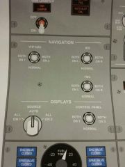
Navigation Panel
|
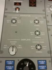
VHF NAV selector switch:
Normal: VHF nav source is from on side nav receiver BOTH ON 1 OR 2: Both sides on Nav 1 or 2 FMC Source selector switch: normal: left FMC controls CDUs and provides input to the autothrottle system, right FMC operates in sync with left FMC Both on L or R: selected FMC controls all FMC operations. FMC L OR R DISPLAYED ON OPPOSITE MAP DISPLAY. note: moving source selector switch will disengage LNAV and VNAV IRS TRANSFER SWITCH NORMAL: flight instruments provided on side pitch and cross side roll information. provides hardover protection. Both on L or R: flight instruments attitude and heading source to selected IRS. can not use the autopilot with both on L or R. |
|
|
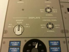
Displays Panel
|
Source Selector:
All on 1: all displays operate on DEU1 All on 2 : all displays operate on DEU2 Normal: DEU 1 provides info for capt's PFD and ND, and upper MFD. DEU 2 provides info for FO's PFD and ND and lower MFD. Control Panel: Both on 1: capts and fo's display units are controlled by capts side EFIS contol panel Both on 2: capts and fo's display units are controlled by FO's EFIS control panel. normal: on side EFIS panel controls on side displays. |
|
|
REDUNDANT LANDING GEAR INDICATOR LIGHTS
|
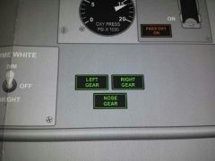
Illuminated
indicates related gear is down and locked. LG is down and locked as long as one green landing gear indicator light (center panel or overhead panel) for each gear is illuminated Extinguished landing gear is not down and locked |
|
|
Fuel Panel
|
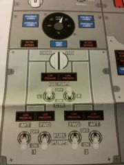
ENG VALVE CLOSED and SPAR VALVE CLOSED
extinguished: related valve is open illuminated: bright: related valve is in transit OR valve position and engine start lever or fire switch positions disagree. dim: related valve is closed Fuel Temp indicator indicates temp in the #1 tank (crossfeed) VALVE OPEN light extinguished : valve is closed illuminated: bright: valve is in transit or valve position and crossfeed selector disagree dim: valve is open FILTER BYPASS lights extinguished: filter operating normally illuminated: impending fuel filter bypass due to contaminated filter CROSS FEED SELECTOR closes or opens the crossfeed valve Center Tank FUEL PUMP LOW PRESSURE lights illuminated: FUEL PUMP switch is ON and fuel pump output pressure is low (light only armed when switch is in ON) (*illumination of both LOW PRESSURE lights with their switches in the ON position will illuminates MC and FUEL SYSTEM lights. With one pump on and one off, if the operating pump gets LOW PRESSURE, MC and FUEL will illuminate ) extinguished: fuel pump output pressure is normal or the switch is OFF Main tank LOW PRESSURE Lights illuminated: fuel output pressure is low OR FUEL PUMP switch is OFF *two LOW PRESSURE lights illuminated in same tank illuminate MC and FUEL annunciator lights. One LOW PRESSURE light will cause MC and fuel to illuminate on MC recall. extinguished: fuel pump output is normal Fuel Pump Switches On- ACTIVATES the pump. AC POWERED OFF- deactivates the pump |
|
|
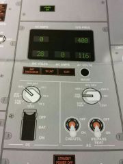
AC and DC Metering Panel
|
DC Ammeter
indicates amperage of source selected by DC meters selector DC Voltmeter indicates voltage of source selected AC Ammeter indicates amperage of source selected by AC meters selector CPS FREQ frequency of source selected BAT DISCHARGE light illuminated with BAT switch ON, excessive battery discharge detected TR UNIT light illuminated -on ground: any TR has failed -in flight: TR1 or TR3 AND TR2 have both failed ELEC light illuminated a fault exists in DC power system or standby power system (*only operates on ground) MAINT TEST SWITCH only used by MX DC SOURCE SELECTOR selects source for DC volts and amps *test used by mx only BAT SWITCH OFF - removes power from BAT BUS and SWITCHED HBB with normal power avail -removes power from BAT BUS, SWITCHED HBB, DC STBY BUS, INVERTER, and AC STBY BUS when bat is only power source. ON (guarded) -provides power to SWITCHED HBB - energizes relays to provide automatic switching of stby electrical system to bat power if normal power is lost AC METERS Selector selects AC source for AC voltmeter, ammeter and freq meter *test used my mx only CAB/UTIL Switch ON/OFF- connect , removes power from galley and cabin equipment galley busses IFE/PASS SEAT switch ON/OFF - connects, removes power from in flight entertainment and pax seats |
|
|
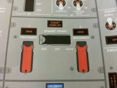
GENERATOR DRIVE AND STBY POWER PANEL
|
Generator DRIVE lights
illuminated IDG low oil pressure caused by -IDG failure -engine shutdown -IDG automatic disconnect due to high oil temp -IDG disconnected through DISCONNECT switch DISCONNECT switch disconnects IDG if electrical power is avail and engine start lever is in idle. CANNOT be reconnected in the air STANDBY POWER OFF light illuminated one or more of the following busses are unpowered: -AC STBY BUS -DC STBY BUS -BAT BUS or Stby power switch in OFF position Standby Power Switch auto- allows automatic switching to battery power if normal AC source for STBY buses fail or are turned off off- dc standby and ac standby busses not powered. bat- if automatic switching to standby power fails, can be used to power the standby system |
|
|
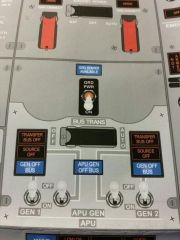
Ground power and Bus switching panel
|
GROUND POWER AVAILABLE light
illuminated: ground power is connected and meets airplane power quality standards GRD POWER switch OFF - DISCONNECTS ground power from AC transfer busses ON - removes previously connected power source from AC busses and then connects ground power to AC transfer busses TRANSFER BUS OFF light illuminated- xfer bus is not powered SOURCE OFF light illuminated: no source has been manually selected to power the transfer bus, or the source has been disconnected. If the opposite xfer bus has been powered by a source, both busses are powered. GEN OFF BUS illuminated: IDG not supplying power to the related transfer bus. GEN Switches OFF- disconnects IDG from related AC trasfer bus by opening generator control circuit breaker ON- connects IDG to related AC transfer bus by disconnecting previous power source and closing gen circuit breaker. BUS TRANSFER switch AUTO- BTB operate automatically to maintain power to AC transfer busses from any operating gen or ext power -DC cross tie relay automatically provides normal or isolated operation as req OFF- isolates AC TRANSFER 1 FROM AC TRANSFER 2 if one IDG is supplying power to both AC transfer busses. -DC cross tie relay opens to isolate DC 1 from DC 2. APU GEN OFF BUS light illuminated APU is running and not powering a bus. APU GEN switches OFF- (while APU powering both AC transfer busses) moving ONE switch to off illuminates the SOURCE OFF LIGHT. APU continues to power both xfer busses. moving BOTH switches to off disconnects APU power from both AC transfer busses. OFF (while one IDG powering a AC transfer bus) -IDG will now power both busses ON (neither AC transfer bus powered by an IDG) single switch on connects both AC transfer busses to APU gen, disconnects ext power, and opposite SOURCE OFF light illuminates until switch is moved to on. (AC busses powered by IDGs) related bus will receive power from the APU gen, other side will stay on IDG. Automatic On-line feature: one time switching from APU to engine IGDs in flight if IDGs are not selected on before takeoff and APU fails. |
|
|
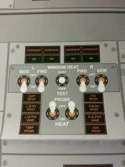
Window heat panel
|
OVERHEAT lights
illuminated: an overheat condition is detected, also illuminates if electric power to window is interrupted Green ON lights illuminated: window heat is being applied to selected windows extinguished: -switch is off -overheat detected -system failure -system is at correct temp WINDOW HEAT SWITCHES ON/OFF- applies, disconnects electric heat to selected windows WINDOW HEAT TEST SWITCH OVHT : Simulates an overheat condition pwr test: provides a confidence test |
|
|
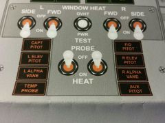
Pitot Heat Panel
|
Probe heat lights
illuminated: related probe not heated. if on stby power heat lights do not indicate system status probe heat switches ON/OFF: power supplied or removed from system |
|
|
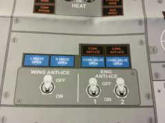
Engine and Wing Anti Ice Panel
|
wing L AND R VALVE OPEN lights
illuminated: Bright: wing anti ice valve in transit or disagrees with switch dim: valve open extinguished: valve closed Wing Anti Ice Switch OFF - valves are closed ON (air logic) -WAI valves open -stick shaker set for icing and remains set regardless of positioning of the switch ON (ground logic) -open at low thrust setting -closed above TO thrust warning setting or thermal trip off - switch trips OFF at lift off Engine Anti Ice Panel COWL ANTI ICE illuminated: overpressure condition in cowl anti ice duct COWL VALVE OPEN illuminated BRIGHT: cowl valve in transit or disagree with switch position DIM: cowl valve open extinguished : cowl valve closed, switch off Engine Anti Ice Switches ON - engine anti ice valve is open -stick shaker ser for icing OFF -engine anti ice valve closed -stick shaker logic returns to normal if wing anti ice has not been used in flight |
|
|
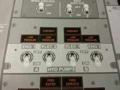
Hydraulic Panel
|
OVERHEAT lights
illuminated: hydraulic fluid used to cool and lubricate the electric motor driven pump has overheated or the pump itself has overheated LOW PRESSURE light -electric pump: output pressure of the pump is low, always armed. If pump is selected OFF, light illuminates. -engine driven pump: output pressure of the pump is low. If fire switch is pulled, low pressure light is deactivated. ELEC Hydraulic Pump Switches ON/OFF- provides or removes power to associated electric motor pump. (ELEC 2- part of system A, powered by AC Transfer Bus 2. ELEC 1- part of system B, powered by AC Transfer Bus 1) Engine Hydraulic Pump Switches ON- pump is running on accessory section of engine already, switch actually de energizes blocking valve in pump to allow pump pressure to enter system. OFF- energizes blocking valve to block pump output. If electrical power to switch/solenoid fails, pump blocking valve fails to open position |
|
|
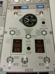
Bleed Air Controls and Indicators
|
Recirculation Fan Switches
OFF- fan signaled off AUTO: IN FLIGHT: -left fan shuts down if either pack switch is in high -right pack switch shuts down if BOTH pack switches are in high ON GROUND -left fan shuts down if BOTH pack switches are in high -right fan operates even if BOTH pack switches are in high DUAL BLEED light illuminated: -APU Bleed open and engine 1 bleed open -APU bleed open and engine 2 bleed open with isolation valve open -APU bleed open, ext pneumatics connected and isolation valve is open RAM DOOR FULL OPEN light Illuminated: ram door in full open position (typically on ground) ISOLATION VALVE Switch CLOSE: closes isolation valve AUTO: -closes isolation valve if both BLEED air switches are on and both PACK switches are AUTO or HIGH -opens isolation valve automatically if either BLEED air or PACK switch is positioned to off. OPEN: OPENS isolation valve L and R PACK switches OFF: Pack signaled off AUTO: -both packs operating, each pack regulated to low flow -one pack operating, pack regulates to high flow in flight with flaps UP -on one pack fed by APU (and both eng bleed switches OFF ), pack regulates to high flow HIGH: -pack regulates to high flow -provides max flow in ground with APU BLEED air on. -*LIMITATION HIGH must not be selected for TAKEOFF, APPROACH, OR LANDING WING BODY OVERHEAT light left- overheat from bleed air duct in left engine strut, left inboard wing leading edge, left air conditioning bay, keel beam, or APU bleed air duct right- overheat from bleed air duct leak in right engine strut, right inboard wing leading edge, or right air conditioning bay. Engine BLEED air switches OFF - closes engine bleed air valve ON- opens engine bleed air valve when engines are operating APU BLEED air switch OFF- Closes APU bleed air valve ON- opens APU bleed air valve when APU is operating Bleed Air Duct Pressure Guage indicates pressure in L and R bleed air ducts WING BODY OVHT TEST switch -tests wing body overheat circuits -illuminates both WING BODY Overheat lights BLEED TRIP OFF light illuminated: excessive engine bleed air temp or pressure -engine bleed valve closes automatically -requires reset PACK trip off light illuminated: indicates pack temp has exceeded limits (excessive temperature in air cycle machine at compressor discharge or turbine inlet) or failure of primary and secondary controls -pack valve closes automatically and mix valves drive full cold -requires reset TRIP RESET button -resets BLEED TRIP OFF, PACK trip off and DUCT OVERHEAT lights -related engine bleed valves, pack valves, or air mix valves open - lights remain illuminated until reset |
|
|
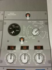
Air Temperature Control Panel
|
Air Temperature indicator gauge
-indicates temp at location selected with AIR TEMP source selector AIR TEMP SOURCE displays the temp of the selected source TEMP SELECTOR ( CONT, FWD, AFT CABIN) AUTO: provides automatic temp control for the associated zone OFF: closes the associated trim air modulating valve TRIM AIR switch: ON/OFF : trim air regulating and shutoff valve signaled open or closed ZONE TEMP lights CONT CABIN: 1.indicates a duct temp overheat 2. failure of the flight deck primary and stby temp control 3. selection of zone temp switch to OFF FWD OR AFT CABIN: indicates duct temp overheat illuminated during MC recall: will extinguish when reset: CONT CABIN: failure of primary OR stby temp control FWD OR AFT CABIN: Failure of the associated zone temp controller |
|
|
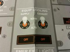
Equipment Cooling Panel
|
SUPPLY and Exhaust switches
NORM: normal fan activated ALTN: alternate fan activated OFF lights illuminated: no airflow from selected cooling fan. altn must be selected |
|
|
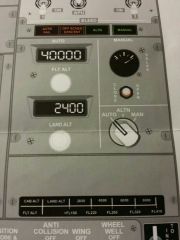
Cabin Pressurization Panel
|
AUTO FAIL light
illuminated: automatic pressurization system failure detected -indicates a single controller failure when ALTN light is also illuminated -indicates dual controller failure if illuminated alone Conditions : -excessive rate of cabin change -loss of dc power -controller fault -outflow valve problem -high differential pressure -cabin alt above 15800 OFF SCHED DESCENT light illuminated: airplane descended before reaching the planned cruise alt set in the FLT ALT window ALTN light illuminated: Pressurization system operating in alternate automatic mode, or mode selector in ALTN position MANUAL light illuminated: Pressurization mode operating in manual mode Pressurization mode selector AUTO: Pressurization controlled automatically ALTN: Pressurization system operating on ALTN controller MAN: Pressurization system controlled manually by outflow valve switch, both auto controllers bypassed OUTFLOW VALVE SWITCH opens or closes the outflow valve electrically with mode selector switch in man OUTFLOW Valve Position Indicator indicates position of outflow valve, operates in all modes Flight Altitude Selector sets planned cruise alt Landing Alt Selector sets planned landing field alt Cabin/flight alt placard used to set cabin alt while in manual mode |
|
|
Displays Panel
|
Two DISPLAY ELECTRONIC UNITS INSTALLED
#1 controls capt outboard, inboard, and upper du #2 controls fo outboard, inboard and lower du Source Selector can be used to select all displays to one DEU Control Panel select switch determines which EFIS control panel controls pilots display functions |
|
|

PSEU light
|
illuminated
on ground: -fault detected in PSEU -overwing exit lock failed to disengage when commanded in flight: inhibited from thrust lever advance for takeoff to 30 sec after landing |
|
|
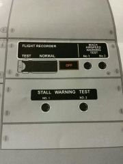
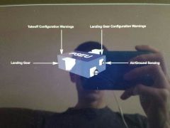
Mach Airspeed Warning Test
Stall Warning Test Switches Flight Data Recorder |
Mach Airspeed Warning Switches
tests respective mach/airspeed warning system, clacker sounds. inhibited while airborne Stall Warning Test Switches on ground: each switch tests respective Stall Management Yaw Damp (SMYD) COMPUTER, 1 SHAKES CAPTS COLUMN, 2 SHAKES FO COLUMN . INHIBITED AIRBORNE Flight Data Recorder on ground , begins recording with engine oil pressure detected. test: bypasses oil pressure switch to test recorder OFF light- -system failure without normal electrical power, -recorder is unpowered. - loss of input data to the recorder -electronic malfunction |
|
|
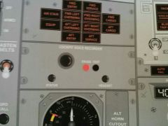
Cockpit voice recorder
|
receives poweranytime 115VAC applied to the airplane. 120 min of recorded data, loops over old data.
test: a tone will be heard if a headset is plugged into the headset jack erase: can be used only if airplane is on ground with parking brake set, hold for 2 seconds |
|
|
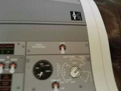
Voice recorder switch
|
auto: powers the cvr from first engine start until 5 min after last engine shutdown.
on: powers the cvr until first engine start, then trips the switch to auto. |
|