![]()
![]()
![]()
Use LEFT and RIGHT arrow keys to navigate between flashcards;
Use UP and DOWN arrow keys to flip the card;
H to show hint;
A reads text to speech;
16 Cards in this Set
- Front
- Back
|
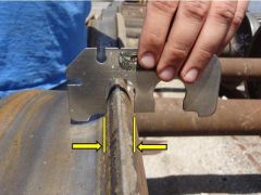
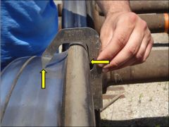
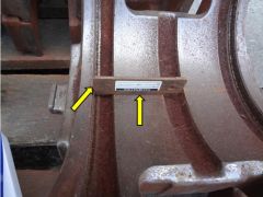
Distance between arrows must be greater than 15/16” with gage in proper orientation. Rule 41.A.1.a Wheel Defect Gage (34401A) Thin Flange |
|
|
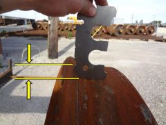
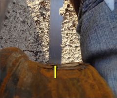
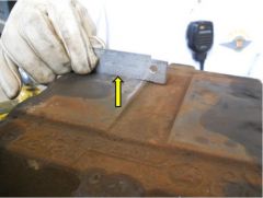
Must not have flat vertical surface extending 1” or more from tread. Rule 41.A.1.b Wheel Defect Gage (34401 A) Vertical Flange |
|
|
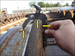
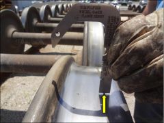
Vertical distance from tip of gage (approximate tread center line) to top of flange must be less than 1 ½” Rule 41.A.1.c – Steel Wheel Gage (High Flange) |
|
|
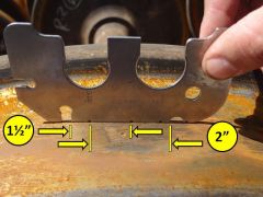
Must not have a slid flat greater than 2” in length; nor 2 or more adjoining spots each greater than 1 ½”. Rule 41 Handling Line Responsibility Wheel Defect Gage (34401A) Flat Spot |
|
|
Measurement at back face of rim must not be ¾” or less for 30” and 33” wheels; must not be 7/8” or less” for 28”,36”, and 38” wheels Rule 41.A.1.h – Simplified Steel Wheel Gage (Thin Rim) |
|
|
Must not have built up metal of 1/8”or higher than the wheel tread Rule 41.A.1.j Simplified Steel Wheel Gage (Built-up tread) |
|
|
Must not have any grooves with a depth of 1/8” or more Rule 41.A.1.k – Simplified Wheel Gage (Groove Tread) |
|
|
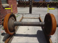
Distance between arrows must not be less than 52 15/16” or in excess of 53 3/16” Rule 41.A.1.q – Wheel Back to Back Limit Gage |
|
|
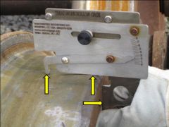
Must not have an indication greater than 4 MM as indicated on the scale on gage. Rule 41.A.2 – Tread Worn Hollow Gage |
|
|
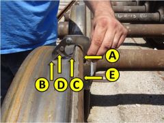
With gage as shown, scale at ‘D’ indicates amt of metal to remove to restore contour; Scale at ‘E’ indicates rim thickness prior to turning
Rule 41.C.4 Steel Wheel Gage (Recondition and Rim Thickness) |
|
|
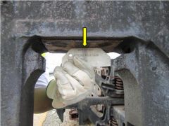
Gage must not rock or contact roof at center Rule 48.A.3.b -Pedestal Ceiling Wear Gage |
|
|
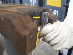
Gage must not contact cast relief areas in between Crowns Rule 37.A.3.a - Bearing Adapter – Body Wear |
|
|
Must not be more than .025” wear at thrust shoulder; must have 1/32” or greater depth of machined relief Rule 37.A.3 - Adapter Wear Gage |
|
|
Gage must contact fully along side between Rule 37.A.3.f - Bearing Adapter – Body Wear |
|
|
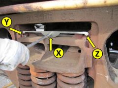
Point X of gage must contact bolster while Y and Z rest upon top of wedges; permissible to have gaps under ends of gage but not under center of gage Rule 46 – Wedge Rise Gage (Standard Truck) |
|
|
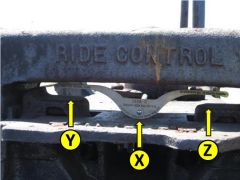
Point X of gage must contact bolster while Y and Z rest upon top of wedges; permissible to have gaps under ends of gage but not under center of gage Rule 46 – Wedge Rise Gage (Ride Control) |