![]()
![]()
![]()
Use LEFT and RIGHT arrow keys to navigate between flashcards;
Use UP and DOWN arrow keys to flip the card;
H to show hint;
A reads text to speech;
163 Cards in this Set
- Front
- Back
|
What kind of contrast agent is air |
negative
|
|
|
is iodine contrast only ionic? |
no |
|
|
Prior to the administration of intravenous contrast, you should assess the patientfor: |
allergies and treatment function |
|
|
The hyoid bone is located at what vertebral level? |
c3 |
|
|
The SSN corresponds to vertebral level: |
T3 |
|
|
what kind of device is a Head holder |
positioning device |
|
|
What positioning device is used to move a patient’s small bowel out of pelvictreatment fields? |
belly board |
|
|
Thermoplastic immobilization devices are used to immobilize the: |
head and neck |
|
|
what controls density of the image |
mAs |
|
|
is taking orthogonal images a part of CT simulation |
no |
|
|
After CT simulation, what must be documented by the radiation therapist? |
patient setup |
|
|
is margin of motion included in the CTV |
no |
|
|
What volume accounts for the patient’s physiologic movement, such as breathing? |
internal margin |
|
|
What term describes critical structures in or near the treatment field? |
organs at risk |
|
|
Plan is optimized after fields are designed |
forward planning technique |
|
|
what is the associated vertebral body for the external auditory meatus? |
C1 |
|
|
what is the associated vertebral body for the thyroid cartilage? |
C4 |
|
|
what is the associated vertebral body for the cricoid cartilage |
C6 |
|
|
what is the associated vertebral body for the vertebral prominence |
C7 |
|
|
what is the associated vertebral body for the SSN |
T2-T3 |
|
|
what is the associated vertebral body for the carina |
T4-T5 |
|
|
what is the associated vertebral body for the xiphoid |
T10 |
|
|
what is the associated vertebral body for the Umbilicus |
L4
|
|
|
what is the associated vertebral body for the bifurcation of the abdominal aorta |
L4 |
|
|
what is the associated vertebral body for the superior ilac crest |
L4 |
|
|
how does negative contrast appear on images |
dark as it absorbs less radiation than tissue |
|
|
how does positive contrast appear on images |
white |
|
|
what about the atomic number of positive contrast agents |
they are very high |
|
|
is the quantity of beam and controls overall density. |
Milliamperage (mA) |
|
|
is the quality of beam and controls contrast. |
Kilovoltage potential (KvP) |
|
|
the 15% rule of imaging |
an increase of 15 % of KvP should also include a decrease of mAs by 50 %. |
|
|
tumor itself |
Gross tumor volume (GTV) |
|
|
GTV + margin to include anatomy which may have microscopic disease |
Clinical target volume (CTV) |
|
|
CTV + margin for setup uncertainty or patient movement |
Planning target volume (PTV) |
|
|
margin to account for patient’s physiologicmovement |
Internal margin (IM) |
|
|
CTV + IM |
Internal target volume (ITV) |
|
|
anatomy receiving prescription dose |
Treated volume |
|
|
area that receives dose significant to normal tissue tolerance |
Irradiated volume |
|
|
critical structures in or near treatment field |
Organs at risk (OAR) |
|
|
the computer program designs beams, based on criteria set at beginningof planning session; used for IMRT treatment planning. |
inverse planning |
|
|
When designing fields and beam arrangements, one must consider |
dose and fractionation scheme isocentric or isometric setup modality (photonsor electrons) beam energy number of fields needed to decrease dose to normaltissue fixed or rotational beams, field weighting, and beam attenuation in tis-sue. |
|
|
Rotational fields are useful for |
central, well-defined tumors |
|
|
in rotational fields the isocenter is placed |
past tumor (past-pointing) to ensure point of highest dose is in thetarget. |
|
|
used to compensate for missing tissue or increase dose toskin |
bolus |
|
|
Blocks are ____ HVL thick. |
5 HVL |
|
|
Blocks must transmit what percent of the treatment beam |
less than 5 % |
|
|
Custom blocks are made of |
cerrobend and lipowitz metal |
|
|
These divergent blocks can be |
positive or negative |
|
|
positve blocks |
(block center of field) |
|
|
negative blocks |
block outside of field |
|
|
MLCs are made of |
tungsten |
|
|
used to alter isodose distribution in patient or compensate for sloping surfaces |
wedges |
|
|
limitations of physical wedges |
field size limitations |
|
|
the thicker part of the wedge |
heel |
|
|
the thinner part of the wedge |
toe |
|
|
When compensating for a sloping surface, theheel is placed |
towards area missing tissue |
|
|
when the jawof collimator moves during treatment to simulate a wedge in treatment field. |
Dynamic wedges |
|
|
when two fields use wedges to modify the isodose distribu-tion |
wedge pairs |
|
|
the angle between two fields |
hinge angle |
|
|
The formula for hingeangle= |
180°−(2×wedge angle) |
|
|
When using wedge pairs, heels are placed |
together |
|
|
The _______________ is the projection of what the treatment field will looklike, from the point of view from the origin of the beam. |
beams eye view |
|
|
graphical representation of how dose is deposited within the tissue. |
isodose distributions |
|
|
graphical representation of volume of organ vs. dose received. |
Dose Volume Histograms (DVH) |
|
|
The radiation therapy treatment prescription must include |
treatment volume and dose fractionation scheme (number of fractions, dose per fraction and scheduling of fractions), information regarding treatment (mode and energy of radiation and beam modifying devices). |
|
|
used for dose calculations.This takes into account different scattering properties of different shaped fields. |
The equivalent square of treatment fields |
|
|
formula for equivalent square of field |
4 × (area of field/perimeter of field) 4 x (ab/(2x(a+b)) |
|
|
the ratio of dose at dmax for field size to dose at dmax forstandard field size (typically 10 × 10 cm). |
output factor |
|
|
Output factor may also be referred to |
Sc (collimator scatter factor) |
|
|
1 cGy/MU at dmax with10 × 10 cm field |
Output factor |
|
|
how does field size effect output factor |
as fs increases OF increases |
|
|
the ratio of dose at dmax in phantom to dose atdmax in air, and may be referred to as peak scatter factor |
BSF- back scatter factor |
|
|
BSF is dependent of___ ____ but independent of ____ |
energy and field size SSD |
|
|
Sp (phantom scatter factor)= |
ratioof BSF for given field to BSF for reference field (usually 10×10 cm). |
|
|
the ratio of dose with modifier in beam to dose withoutmodifier in beam and used for wedges, block trays, and compensators. |
attenuation factor |
|
|
the ratio of absorbed dose at depth to dose at dmax. |
percent depth dose (PDD) |
|
|
Percent depth dose increases with increased |
energy, field size, |
|
|
PDD decreases with increased |
depth and SSD |
|
|
used for SSD calculation when the patient is treatedwith a different SSD |
Mayneord’s factor |
|
|
Mayneord’s factor formula = |

|
|
|
the ratio of dose at depth in phantom to dose at depthin air. |
Tissue-air ratio TAR |
|
|
the ratio of scattered dose at depth in phantom toscatter dose at depth in air and used for irregularly shaped fields. |
Scatter-air ratio SAR |
|
|
the ratio of dose at depth to dose at dmax, while tissue-phantomratio
|
Tissue Maximum Ratio TMR
|
|
|
the ratio of dose at depth to dose at reference depth. |
tissue-phantom ration (TPR) |
|
|
TAR is independent of |
SSD |
|
|
when is TAR = BSF |
when measured at dmax. |
|
|
TAR increases with increased |
energy and increased fieldsize, |
|
|
TAR decreases with increased |
depth |
|
|
When is TAR used |
factor is used in SAD calculations |
|
|
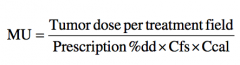
Formula to calculate monitor units for SSD treatments |
|
|
|
Formula to calculate monitor units for SAD treatments |
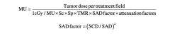
|
|
|
Range of electrons is based on |
energy |
|
|
The practical range (Rp) is the depthelectrons travel in tissue, and is calculated by |
MeV of beam/2. |
|
|
The depth of80 % isodose curve= |
MeV of beam/3 |
|
|
the depth of 90 % isodosecurve = |
MeV of beam/4 |
|
|
Information used in electron calculations include |
tumor dose per fraction depth of target cone size and blocking factors (Cfs) and calibration factor (Ccal) (typically 1 cGy/MU). |
|
|
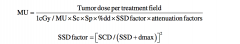
formula used to calculate monitor units for electron treatments |
|
|
|
when simulating a patient for IMRT what should the slice thickness be |
2-3mm to provide enhanced detail and optimal density differentiation for heterogenic dose calculations |
|
|
what slice thickness may be used for nonIMRT plans |
5mm slice thickness |
|
|
delineation of the treatment target and the placement of the isocenter relative to the target is referred to as |
localization |
|
|
the transverse axis that extends right to left in the patient |
X |
|
|
the longitudinal axis extending heat to foot |
Y |
|
|
axis extending upward from the bale top |
z |
|
|
if the patient is laying supine and head first on the table, the positive x-axis is on the patient's |
left side
|
|
|
if the patient is laying supine and head first on the table, the positive y-axis is |
cephalic |
|
|
if the patient is laying supine and head first on the table, the positive z-axis is |
anterior |
|
|
patient marks can be applied with |
felt pens, paint pens, carfusion, or tattoos |
|
|
knee supports should be avoided when the treatment site is where |
below the diaphragm, leg elevation can cause variation in the location of the internal anatomy in the abdomen and pelvis |
|
|
while the mask is cooling use fingers to mold at the |
glabella, chin, and entry of the auditory meatus |
|
|
for breast setups what would cause the torso to roll |
crossing legs at the ankles |
|
|
with 3D treatment planning computers, breast board elevation can be kept |
at a minimum of 5-10 degrees |
|
|
for treatment of the pelvic region, vacloc bag should extend from |
the buttocks to the feet |
|
|
what helps the feet from rotating laterally in pelvic setups |
rubberband around the feet |
|
|
how wide is the bellyboard cut open |
30 x 30cm |
|
|
the bottom edge of the belly board should be at the level of
|
the illiac crest |
|
|
Barium is inert, what does this mean |
lacking the ability or strength to move
|
|
|
perforation is suspected, can barium be used? |
no |
|
|
which functions should be tested before applying iodinated contrast |
liver and kidney functions |
|
|
what are the lab works done before contrast is administered IV-ly |
BUN and creatinine |
|
|
what is determined during conventional simulation |
fs, gantry angle, collimator angle, table angle, treatment depths, and blocking |
|
|
the equivalent square of the unblocked portion of the treatment fielf |
effective square |
|
|
Wedge Fector is dependent on |
wedge angle fs beam energy |
|
|
if MLC is used is a tray factor used? |
no |
|
|
inverse square formula |
[(old SSD + Dmax)/(new SSD + Dmax)] squared |
|
|
higher energy photons are better suitable for which sites |
abdominal and pelvic |
|
|
lower energy photons are suitable for which sites |
head and neck, breast, superficial targets |
|
|
what is the depth of electronic equilibrium |
Dmax |
|
|
skin sparing is a result of |
Dmax |
|
|
when should the horizontal axis be parallel to the treated surface; en face |
when using electron fields |
|
|
wedge thickness and distribution |
the thicker the wedge, the more dose distribution is effected |
|
|
how is the angle of the wedge described |
the angle of the 50% isodose line at the central axis for low energy beams or the angle of the dose line located at 10cm beneath the surface of the central axis for high energy beams |
|
|
to prevent undue electron scatter skin contamination where should the wedge be placed |
no closer than 15 cm to the patient |
|
|
what percent of the perscribed dose should be covered when determining the expansion of the field size |
no less than 95% of prescribed dose |
|
|
any tissue recieving greater than 50% of the dose |
irradiated volume |
|
|
the CTV with additional 0.5 cm margin |
PTV |
|
|
two or more plans combined to show summative doses for all phases of the treatment regimen |
composite plan |
|
|
examples of dynamic therapy |
IMRT, rapid arc, and tomotherapy |
|
|
three methods to reduce or eliminate overlapping dose regions |
calculation of surface skin gaps calculation of beam divergence with implementation of couch kicks or gantry angles use of half field technique |
|
|
Beam divergence formula |
tan -1 (A/2SSD) A= dimension of the treatment field for which divergence is computed |
|
|
Skin gap formula |
.5A1 x (d/SSD) + .5A2 x (d/SSD) |
|
|
what field arrangment is used when the tumor is centrally located with no dose limiting structures in the path such as the whole brain, humerus, femur, breast |
Parallel opposed pair |
|
|
what field arrangment is used when the tumor is deep seated with dose limiting tissues surrounding such as the prostate, bladder, and endometrium |
4 field box |
|
|
what field arrangment is used when the tumor is deep with dose limiting tissues on one side, such as in treating the pancreas with sensitive kidneys posterior, rectum with sensitive small bowel and bladder anterior |
3 field with 90 degree hinge |
|
|
what field arrangment is used when the tumor is unilateral such as laterally located primary brain tumors, maxillary sinus |
2 field with 90 degree hinge |
|
|
what field arrangment is used when the tumor is small, deep targets like the prostate, cervix, pituitary gland with sensitive tissues all around |
arcs or mutiple field IMRT |
|
|
concentrated dose toward the center sparing tissue in the periphery |
arcs of mutiple field IMRT |
|
|
what field arrangment is used when the tumor is near the surface such as thoracic spine, upper lumbar spine, superficial supraclavicular LN |
single field photon |
|
|
what field arrangment is used when the tumor is treatment of superficial targets; bolus may be applied to eliminate skin-sparing at the surface |
single field electron |
|
|
rapid dose fall off; maximum dose near the surface |
single field electron |
|
|
removable grids used in therapeutic linacs to broadcast crosshairs onto a portal image |
BB tray fiduciary tray graticule |
|
|
SAD is measured from the ___ to ___ around which the gantry rotates 380 degrees |
focal spot, point |
|
|
what straightens the lordotic curvature of the spine, making the patient more comfortable during the treatment |
knee sponge |
|
|
T or F. Allowing the breast to find natural position is more reproducible |
T |
|
|
for nonisocentric treatments what is the factor of choice to demonstrate central axis dose at a given depth |
%DD |
|
|
when looking up the %dd or the TMR for a given depth and fs what should be used when there are blocks or MLCs |
Effective Square |
|
|
sterlings formula calculates |
equivalent square |
|
|
when using MF what %DD for what field size is used |
new %DD for fs at a new distance |
|
|
when using MF what happens to the inverse square |
change inverse square to reflect new SSD |
|
|
Applied dose formula |
AD=TD/PDD |
|
|
the energy loss of MV electron beams in water is approximately |
2 MeV/cm |
|
|
when more than two planes of a sources are used this is called |
Volume implant |
|
|
formula for exposure at a specific distance |
activity/distance squared |
|
|
manual contouring with |
solder wire calipers plaster of paris |