![]()
![]()
![]()
Use LEFT and RIGHT arrow keys to navigate between flashcards;
Use UP and DOWN arrow keys to flip the card;
H to show hint;
A reads text to speech;
52 Cards in this Set
- Front
- Back
|
Induction motors |
A electrical motor that converts electrical power(energy) into mechanical power(energy). That gets energy into the rotating part by mutual energy, the transfer of energy from the stationary part to the rotating part using transformer action. |
|
|
Torque |
Induction motor rotates, it creates a rotational motion call torque ( also called the moment of force). Rotational motion is the result of interacting driving and restraining force. |
|
|
Torque on a conveyor belt |
If load in increase then the counter-torque increase and the motor responds by slowing down
Moter draw more current witch increases the torque to match the higher counter torque but at a lower speed.
If the counter-torque is decreases the motor responds and the convertor belt is at a higher speed |
|
|
Prony brake |
Measures a motor torque. The mechanical load is a drum that has a belt partially wrapped around it to create a counter-torque. Tightening or loosening the belt adjusts the prony brake counter-torque. The mechanical power of the drive motor can be calculated
T= F×r T- newyon-metres F- newton's r- metres |
|
|
Prony brake alternative |
Is called a dynamometer with is a electric generator, can be adjusted to apply more counter-torque to t he motor shaft. |
|
|
Mechanical power and torque. Deff |
The mechanical power of a rotating machine is the product of rotational speed |
|
|
Mechanical power formula |
P=t×n/9.55
P- watts W T- Nm N- revolution per min r/min 9.55 constant |
|
|
Electrical motor form |
hp= t×n/7121
hp- horsepower T- Nm n- revolution per min r/min 7121- 9.55 times 746 W/hp
|
|
|
Efficiency deff |
Is the ratio of the output of energy over input of energy
|
|
|
Efficiency formula |
%eff= P(out)/ P(in) ×100 |
|
|
Losses |
Losses in and induction motor are electrical and mechanical.
|
|
|
Electrical losses. 2 |
Iron- occur in the stator(stationary iron) and the rotor(rotating) Copper- in the stater and the rotor although the rotor conductor may be made up or alum or brass |
|
|
Mechanical losses. 2 |
Friction- in the bearing and between brushes and slip rings when they are used
Windage- is the energy lost due to the air movement produced by the motor |
|
|
Thre-phase induction motors. 3 parts |
Frame Stator Rotor |
|
|
The frame |
Also called the stator frame or enclosure. Steel structure that hold the stator and the rotor. It includes - the cast or forged steel frame - end brackets (also called end bells) - bearings in the end brackets - junction box
Protect from other mechanical parts from moisture, chemicals mechanical damage and abrasion from grit.
Moat standard motors are drip-proof(dp) and guarded or semi-guarded.
|
|
|
Drip-proof (dp) frames |
Also called open drip-proof(ODP) are suitable for clean,dry and indoor environments. DP motors alloe outside air to: - enter one end of the motor - flow past the stator winding - flow between the stator and the rotor - exit the other end
|
|
|
Totally enclosed Frames |
For outdoor installation or dirty entertainment. Three types of enclosed
Totally enclosed fan-cooled Totally enclosed non-ventilated - textile industry Totally enclosed pipe-ventilated -replace explosion proof motors |
|
|
The stator |
Stationary part of an electrical machine is called the stator. Comprised of the Stationary iron and winding. It produces a rotating magnetic field that intersects the rotor. Stator includes - the laminated and slotted iron - the conductors - the conductors insulation - protective sleeves and wedges for the slot |
|
|
Stator parts |
Laminated and slotted iron The conductors The conductor insulation Protective sleeves and wedges for the slots |
|
|
Stator built with windings |
The windings that fitted into the slots cut into the stator iron.
Standard parts allowing more flexibility and efficient manufacturing
Winding are distributed evenly through the stator witch cancels some harmonics cause by the pole windings.
Improves the efficiency of the motor and the electrical system and reduce interference with other equipment
Two major part are the core and the windings. |
|
|
Stator core |
Provides a high permeability path for the magnetism. Thin silicon steel lamination perpendicular to the rotor shaft. Each laminations is insulated by laminating the surface coating to minimize eddy current and hysteresis losses. Laminations are stacked as full rings or segments ether in the fixture or stator frame |
|
|
Stator winding |
Made up of insulated coils placed in axial slots of the stator core inside diameter
2 different winging methods |
|
|
Lap windings |
Have as many coils as there are slots with each coin identical on size and orientation to all others
Have a identical pitch (span) |
|
|
Concentric winding |
Have coils for each phase for each pole. These become progressively larger while centered on the smallest coil for the phase and pole.
Coil have a varying pitch (span) |
|
|
Stator winding description |
Large motor are always delta connected and small are wye-connected.
Once the winding are in place the stator they are dipped in a tank off varnish or resin and then baked in an oven.
The three-phase induction motor are connected to a three-phase source to produce a rotating magnetic field. This rotating magnetic field has a constant magnitude and rotated at a constant speed called synchronous speed. |
|
|
The rotor |
Squirrel-cage Wound rotors Also include - the laminated iron - the conductors - the shaft |
|
|
Squirrel-cage |
Aluminum or copper bars called rotor conductors or rotor bars. They are placed in the slots on the periphery of the rotor.
To provide mechanical strength, the rotor conductor are brazed, welded or molded to the end ring to form a complete closed cct.
Rotor conductors(bars) are formed when molten aluminum is poured or copper is pressed into slots of the stacked iron lamination. The conductors a are connected on both ends of the drum by end rings. The copper bars are welded and the aluminum are connected when they are molded in the die-cast machine.
The slots are not parallel to each other they are rather a bit of a slant (skewed). The skewing prevents the stator and rotor teeth from magnetic locking.
|
|
|
Squirrel-cage rotor current |
In order for the current to be induced there must be a difference between the rotor speed(n) and the synchronous speed of the stators magnetic field. This difference is called the slip speed.
Current flows from one end to the other in the bars attached to the rings with a north and south pole. Current-carrying conductors are placed within a magnetic field developing a force within them that moving the conductor.
Conductors produces torque that rotates the rotor in the sane direction as the stator magnetic field, but at a lower speed.
A Squirrel-cage motor has an induced current that shift around the rotor at slip speed, witch is the difference between synchronous speed and rotor speed. |
|
|
Wound rotor motor WRM |
Same as the Squirrel-cage but the construction of the rotor.
The WRM had conventional, insulated copper windings that terminate in slip rings.
Carbon brushes connect the rotor cct to external, adjustable resistance.
When a large WRM first started can be connected directly to the supply for starting bc the stator are 150% for the full-load cct.
They require more maintenance due to the more wear or aging of the carbon brushes gliding over the slip rings. Slip speed is typically 2-5% of synchronous speed.
|
|
|
Three-phase Induction motors operation |
Have 3 stages 1- three-phase Ac power supplied to the motor stator creates a rotating magnetic field that is constant in magnitude and rotates at constant speed 2- The induction motor operates as a transformer with a rotating, short circuited 2nd winding.The stater rotating magnetic field cuts rotor conductors. 3- The resistance and inductance of the rotor circuit affects the rotor starting torque and starting current. One started the speed by which the rotor slipped behind the speed of the stater magnetic field is proportional to the load counter-torque |
|
|
Rotating magnetic field |
Magnetic field in the stator windings that induce a voltage(current then flow) in the short-circuited Squirrel-cage rotor bars. Torque is developed in the rotor causing the rotor to turn in the same direction of the magnetic field of the stator. In single-phase winding the increasing and decreasing current and the polarity reversals are copied by the magnetic field.
The polarity and magnitude of the flux produced by the winding is proportional to the winding magnetomotive force or current. Magnetomotice force is the movement of electric charges that creates magnetic flux. - when current is zero, magnetic flux is zero - when current is at it positive max, magnetic field is at its max Magnetomotice force is the movement of electric charges that creates magnetic flux.
|
|
|
Rotor current induction left-hand conductor rule |
View A- indicates electronic flow is towards you Thumb - direction of electron flow Fingers - magnetic lines of force
|
|
|
Left-hand generator rule |
Thumb- relative direction of rotor conductor motion with respect to the external field Forefinger- direction if the magnetic field Middle- direction I'd electron flow |
|
|
Right-hand motor rule |
Thumb- direction if force developed Forefinger- magnetic polarity north-south Middle- direction of current |
|
|
Induction motors as a transformer |
Stator winding of the induction motor is the primary winding and the rotor winding is the secondary winding
Secondary winding of an induction motors is short-circuited. Secondary current is controlled by the slip speed, witch is the difference between synchronous speeded and rotor speed. Secondary current increases when the load counter-torque increase, so the slip speed also increases.
If the slip stream increases greater voltage and current are induced in the rotor winding and the primary current also increases. |
|
|
Motor nameplates |
Information -overcurrent device type and size -starter type and size -overload device or setting -wiring means and conductor type -troubleshot the motor
Also the manufacturer the catalog number specifications and the serial number of the motor. The load on a running motor and the exposure of the motor to excessive temperature or current. |
|
|
Motor frame nameplate. 2 types |
Fractional-horsepower and integral horsepower Fractional-horsepower frames are 42,48,56 The frame refers to the housing of the motor. The codes indicate the mounting arrangement, the mounting-hole placement the fram dimensions, the shaft diameter and the hight to the center of the shaft |
|
|
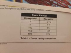
Power rating nameplate |
|
|
|
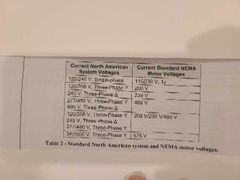
Voltage nameplate |
Regarding variation the NEMA standard states -voltage variations may not exceed (+-) 10% -frequency variation may not exceed (×-) 5% -the combined variation may not exceed (×-) 10% |
|
|
Voltage nameplate |
|
|
|
Current nameplate |
Current us the full-load current. A fully-loaded motor connected to somewhat lower the rated voltage draws more then rated full-load current. Motor draws more current when connected to less voltage bc more current is required to supply the electrical power. |
|
|
% percent speed regulation formula |
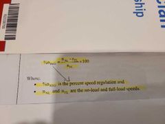
%n= n(no-load) - n(full-load)/ n(full-load) |
|
|
Insulation class |
Class of motor is the temperature of the motor winding, A,B,F,or H H- withstand higher temperature then the other ones A- is rarely used on modern motors B & F- are common H- required to run hot ex- ambient temperature |
|
|
Duty |
Amount of time that a motor can run without cooling period. Motor suitable for continuous duty can run without interruption. Motor can also a short time rating of five to sixty minutes. Duty affects the size of conductors and it insulation of the conductor that is attached to it. |
|
|
NEMA starting code |
National Electrical Manufacturers Association Is the used to estimate a motors expected starting current. Code letter between A and V. A- exceptionally low starting current V- exceptionally high starting current |
|
|
Frequency nameplate |
60 Hz in North America, but if the motor utilizes a variable frequency drive it is designed to operate at varying speeds and the frequency range could be given on the nameplate |
|
|
Rotor design |
Most common design for squirrel cage ARE A,B,C,and D A is normal starting torque but high starting current and can handle brief periods of overload B is common and have normal starting torque and low starting current C is high starting torque, low starting current and are designed for starting heavy loads D is high starting torque, low starting current, and suitable for equipment that requires high inertia start but has poor speed regulation |
|
|
Speed nameplate |
Speed listed l on the name nameplate is the full-load speed. Slip streets that are typically 2-8% of the synchronous speed. The synchronous speed can be determined from the nameplate speed. |
|
|
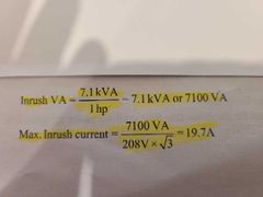
Service factor |
They are classify these motors in standard horsepower sizes. They often don't match the actual power output that the motors can deliver, that deal with this discrepancies with service factor. To figure it out hp ×service factor. Full service factor can be applied when -rated voltage and frequency are applies to motors - line voltages are balanced - ambient temperature is less or equal to 40°C |
|
|
When service factor are meet |
When service factor is maximized for a extend time it can cause sever problems - reduces speed - overheating - deceased efficiency - deceased power factor - shorter life span of the motor |
|
|
Service factor code |
Uses service factor to determine the establish setting or selection of the overload device - motors with 1.15 or grater shall have an overload setting less the or equal to 125% of the full-load current -motors with less then 1.15 shall have an overload setting less the or equal to 115% of the full-load current |
|
|
Motor rotation |
NEMA motor terminology refers to the front and the back of the motor. Front end of the motor is the end without the shaft ICE drive end is with the shaft and the and non-drive end of the motor. |