Reading...
![]()
Play button
![]()
Play button
![]()
Use LEFT and RIGHT arrow keys to navigate between flashcards;
Use UP and DOWN arrow keys to flip the card;
H to show hint;
A reads text to speech;
100 Cards in this Set
- Front
- Back
- 3rd side (hint)
|
What CODEC stand for?
|
Coder/Decoder
|
|
|
|
What do CODEC do?
|
Codec converts analog voice into zeros and ones and decoder converts zeros and one back to analog voice
|
|
|
|
What are the tradeoffs of codecs?
|
Bandwidth – lower is better, but quality may suffer
Quality – higher is better, but that takes more bandwidth and/or more complex (costly) codec Cost – the chips and software that go into the end stations and gateways More complex, more expensive More widely used, les expensive |
|
|
|
What is a low pass filter?
|
All frequencies below will pass and frequencies above will be filtered
|
|
|
|
What is the sampling rate when digitizing voice?
How many samples per second? |
every 125 usec (micoseconds) or 8000 samples per second
|
|
|
|
What is the appropriate sampling scheme?
|
It depends on the human voice.
The human ear can hear 20-20Khz. The typical human voice is <3.4Khz. This allows a low pass filter of 4khz to be used when digitizing voice |
|
|
|
How is it determined that 8000 samples per second is appropriate for human voice?
|
The Nyuist Theorem
|
|
|
|
What is the Nyquist Theorem?
|
If a signal running through a low pass filter of bandwidth H, the filtered signal can be completely reconstructed by making only 2H samples per second.
|
3.4 vs. 4.0 kHz:
Under ideal conditions, a low-pass filter would exactly pass unchanged all slower signal components with frequencies from DC to the filter cutoff frequency. Faster components above that point would be totally eliminated, reducing the signal disturbance. But, real filters do not cut off sharply at an exact point. Instead, they gradually eliminate frequency components and exhibit a falloff or rolloff slope. |
|
|
If a signal consists of V discrete levels, the required bit rate for transmitting the signal is:
|
bit rate = 2 X H X log2V bits/sec (bps)
Example: Voice (low pass filter): 4 kHz Quantization (discrete) level: 256 Bit rate = 2 × 4 (kHz) log2256 = 64K bps |
|
|
|
Show the components of CODEC Operation
What does each component do? |
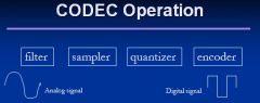
Filter: filter out non-voice signal
Sampler: samples the analog signal at fixed intervals defined by the sampling frequency, FSAMPLE Quantizer digitizes PAM samples into discrete levels. The process results in Quantization noise introduced into signal Encoder: encodes a n bit binary pattern for each quantized sample |
|
|
|
Show a diagram of the Analog to Digital Conversion via Pulse Code Modulation (PCM)
|
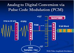
The conversion from analog to digital is called Pulse Code Modulation (PCM).
The four steps in pulse code modulation are: Filtering Sampling Quantizing Encoding |
|
|
|
Show Digitization: Step One
|
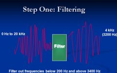
Filtering
Filtering the analog voice signal takes out frequencies below 200 Hertz and frequencies above 3400 Hertz. This is done because: Eliminating low frequencies reduces noise, which may be induced from nearby power lines. Eliminating higher frequencies reduces the number of bits needed to represent the voice signal. Since these higher frequencies are not required, the quality of the received signal is not adversely affected. |
|
|
|
Step Two: Sampling
|
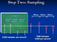
Sampling
The second step is to sample the analog voice signal. The Nyquist sampling theorem tells us that in order to capture enough information about the signal, such that it can be recreated at the distant end of the transmission system, we must sample at a rate equal to or higher than twice the highest signal frequency. We sample at a rate of 8000 samples per second. Each sample is a representation of the original analog signal. A sample is an electrical pulse that corresponds to the amplitude of the analog signal at the moment of sampling. The stream of samples represents the original signal. The pulses are modulated, or varied, exactly in proportion to the amplitude of the analog signal. For that reason, this is called pulse amplitude modulation, or PAM. |
|
|
|
Step Three: Quantizing
|
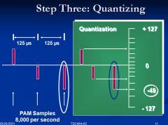
Quantizing
The third step in the conversion process is called quantizing. Quantizing assigns a discrete numeric value to the samples based on their amplitudes. |
|
|
|
Step Four: Encoding
|
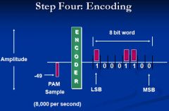
Encoding
The fourth step in the analog to digital conversion process is encoding those quantized samples into eight-bit combinations representing the amplitude level of each sample. |
|
|
|
What is the difference between a-law and -u-law?
|
a-law: the PCM method used in Europe
μ-law – the PCM method used in North America. Their differences are minor, and most devices support both a-law and μ-law. |
|
|
|
What is the most common CODEC scheme?
|
PCM
|
|
|
|
What is the advancement in PCM?
|
ADPCM – Adaptive differential PCM
4-bits sampling, 32K bps vs. 64K bps commonly used on the toll (long distance) network |
|
|
|
What is the advantage of using ASPCM
|
Reduce the bandwiddth by 50% or increase the traffic by 100% using the same facility
|
|
|
|
If you see device that includes specifications for a-law or u-law what does this mean?
|
The device uses a CODEC for converting analog voice to digital
|
|
|
|
What is the bps needed to support Music CD
How much a space on the disk would it take to store one second of music? |
Exercise – Music CD
Hearing Range: 20 -20 kHz Music/CD Quality: 20 kHz Nyquisit frequency: 44.1 kHz (for low pass filter) Sampling: 44.1 kHz (or 44,1000 samples/sec) Quantization Level: 216 (16 bits) 2 stereo channels Bit rate for CD Music: 44,100 × 16 × 2 = 1.4M bps 1.4Mbps X 8= |
|
|
|
Does the music lyric need more or less bandwidth than traditional voice?
|
Usually there is not as much variety as voice communication, so you will need fewer bits to do the coding
You will need same sampling rate, but the CODEC or Quantization will be much lower. The file space will lower and the bandwidth will be lower than voice. |
|
|
|
How does the GSM CODEC copare with PCM?
|
GSM uses only 20% of the bandwidth of PCM
In wireles comuication the object is to reduce the bandwidth. The strategy is get as many users within a given frequency as possible By using more advanced CODEC's such as GSM more users can be supported |
|
|
|
What is the difference between modem and codec?
|
CODEC is analog-to-digital and digital-to-analog
MODEM is digital-to-analog and analog-to-digital Is Modem the reverse of CODEC? No CODEC is based on Nyquist Theorem (sampling) Modem is based on Shannon's Theorem (to use carrier signal to carry data) |
|
|
|
Does cell phone function as a modem or a CODEC?
|
Cell has functions of both CODEC and Modems
3G phones are digital and are using CODEC functions A cell phone uses modem function to take human voice which has been digitized via a CODEC in order transmit as a radio frequency from the phone to the base station or tower |
|
|
|
Does an IP phone function as a modem?
|
No
|
|
|
|
Exam:
Provide seven advantages of voice digitization |
Noise Resistance (reliability)
Can you tell whether a phone call is local or toll by its voice quality? Multiplexing (cost) TDM vs. FDM, lower cost for TDM-circuitry Security – via encryption Higher throughput (more calls on the same physical media) through voice Compression Algorithms Network Convergence Voice Packetization: difference between voice digitization and voice packetization Integrated services Performance Monitoring Network Management |
|
|
|
Why is Noise Resistance and advantage in digitization
Can you tell whether a phone call is local or toll by its voice quality? |
Analog signal degrades over distance. Analog needs amplifiersover long distance. Amplifier also amplify the noise
In the case digital communication distance is not a factor No. |
|
|
|
Why is Multiplexing important
|
By using digital communication you use multiplexing technologies, such as Time Divisoin Multiplexing. This makes more effecient use of bandwith.
In the case of analog you only do frequency division multiplexing. |
|
|
|
What some examples of higher throughput?
|
Using CODECs to reduce bandwith ADPCM reduces bandwith by 50% and GSM which reduce bandwidth requirement by 80%
|
|
|
|
What are the issues (disadvantages of Digital Transmission?
|
Digital transmission facility
Introduction of Quantization Noise Need for synchronization whenever a digital signal is transmitted across a channel, a timing reference (“clock”) is needed to control the synchronization jitter - digital signals that cannot stay in sync. It degrades transmission quality. The variation of transmission delay that causes the clock out of sync. |
|
|
|
256 vs 65,000
|
voice quantization vs music quantization
|
|
|
|
How are timing and jitter issues addressed?
|
with advancements in semiconductor chip technology. The cost of these solution have come down dramtically
|
|
|
|
Define multiplexing
|
Purpose
Multiplexing serves to more efficiently utilize a transmission channel by allowing more than one “source” to utilize the line Bundle multiple “circuits” into a physical facility (wire |
|
|
|
What are the three types of multiplexing, provide examples
|
Frequency Division Multiplexing (FDM) Radio and TV prior to digital
Time Division Multiplexing (TDM) Wavelength Division Multiplexing (and DWDM) Uses different wave lengths to carry the traffic. By using DWDM can use different wave color to carry multiple signals |
|
|
|
TDM - Data Rate
|
Has many low rate data signals coming in that share a high data rate signal going out. The high data rate channel is divided into many time slots. The low data rate signal are inserted into the time slots
|
|
|
|
What is the difference between a T1 and a DS1?
|
The T1 defines the physical facility (cable) and the Digital Signal 1 DS1 defines the framing format
|
|
|
|
Describe the DS1 Frame Format
|
192 bits (24 × 8 bit channels) + 1 framing bit = 193 bit frame
193 bits frame x 8,000 times per second = 1.544 Mbps. |
Time division multiplexing (TDM) involves sharing a transmission medium by establishing a sequence of time slots during which individual sources can transmit signals--thus, the entire bandwidth of the facility is periodically available to each user for a restricted time period. A device called an Analog-to-Digital (A-D) converter at each end of the transmission performs the conversion between analog and digital formats as required. In many systems, a device called a channel bank contains the A-D converter and performs the TDM functions. In North America, Japan,and Singapore, the DS1 (“digital signal 1”) is the fundamental TDM building block.
In a DS1 signal, 24 PCM bitstreams, (or time slots), encoded with eight bits per sample (the 64 kb/s “DS0s”) are multiplexed together into 192 bit frames (24 x 8 = 192). One additional bit is added to each frame to identify the frame boundaries, producing a total of 193 bits in a frame. The framing bit has an identifiable sequence. In original channel banks, the framing bit alternated between 0 and 1. The frame interval is 125 µs (the sampling is at 8000 samples/sec), and thus the basic DS1 line rate is 1.544 Mb/s. In the DS1 format, each of the 24 time slots is rated at 64kb/s and is often referred to as a trunk. Thus, a single T1 is a 24 trunk span. 24 x 64k = 1.536 Mb/s + 8000 framing bit/s = 1.544 Mb/s. DS0 and DS1 are two levels of a series of standard digital transmission rates called Digital Signal X (see ANSI T1.107). |
|
|
How many wires in a T1 facility?
|
4 wires
|
|
|
|
What are the connector types for a T1 cable?
|
RJ48C/DB15M
|
|
|
|
How is T1 service typically provided today?
|
via HDSL
|
|
|
|
How do the DSU and CSU devices function?
|
Is to convert inbuilding signal to outside signal
Also supports line conditioning and loopback services Also allow the configuration of the number of DS) channels needed |
|
|
|
What device converts multiple voice analog singal channels into the T1
|
a Channel Bank
|
|
|
|
The Channel Bank usually performs the following three functions?
|
CODEC, MUX, and DSU/CSU
|
|
|
|
Why is Channel Bank important
|
Because there will users that want or need analog phone
|
|
|
|
T1 vs. FT1
|
FT1: fractional T1 (n × DS0)
T1 and FT1 requires the same physical facility to provisioned to the customer (i.e., 4-wire) FT1 does not use all 24 channels, and T1 uses all 24 channels. |
|
|
|
Channelized T1 vs Unchannelized T1
|
A T1 line is a synchronous digital transmission running at 1.544 Mbps with certain signal characteristics. It is divided into frames of 192 data bits plus 1 framing bit for a total of 193 bits. There are 8,000 of these frames per second. That gives you 1.536 Megabits of data per second.
Now's where the various flavors of T1 come into play. Many companies use that 1.536 Mbps of bandwidth for what's called dedicated Internet service. The line is dedicated to Internet service and is not shared with other customers. It often is shared within the company by plugging it into a router that has a T1 CSU (Channel Service Unit) and using the router output to feed the corporate network. Using a T1 line as a data pipe is also called "Unchannelized T1" because the 192 bits or 24 bytes per frame are not divided up further by the T1 line equipment. Unchannelized T1 is a fairly recent development. When T1 or Trunk Level 1 was being put into service in the 1950s, it was designed to carry telephone traffic. Each call is separate and distinct, so the T1 frame was divided into 24 channels of 8 bits each. Running at 8 Kbps, that gives each channel a bandwidth of 64 Kbps or just right for one toll quality telephone call. Using a T1 line in this fashion is called "Channelized T1." Channelized T1 is still popular today to provide multiple telephone lines to a PBX system. It replaces up to 24 separate pairs of telephone wires. A single T1 line combining all those phone lines into a single 4 wire line is often considerably less expensive that running them all separately. A PBX system with a T1 interface card will assign the channels as needed to support up to 24 simultaneous telephone calls. |
|
|
|
What are the three flavors of T1?
|
fractional, channleized, and unchannelized
|
|
|
|
What is the difference betwen E1 and T1
|
Similar to T1, used outside North America
The E1 interface provides a 2,048 kbit/s access rate. It can support up to 32 user channels (DS0’s), though mostly only 30 are used for user channels. 64 kbsp × 30 = 1,920 kbps 64 kbsp × 32 = 2,048 kbps The E1 interface supports 3 different kinds of bit structures : Frame, Multiframe (16 frames), and Unframed. |
|
|
|
Show the E1 frame format
|

TS0 is dedicated for synchronization, alarms, control messages, and future extensions.
TS16 is usually used for signaling. It is also known as Clear Channel Signaling, an example of out of band signaling. TS0 and TS16 can carry data as well (unchannelized) TS1-TS15 and TS17-TS31 are used for carrying user data. |
|
|
|
What is a T3?
|
28 T1 muxed together to provide 44.736M bps
Sometime you'll probably see a number between 43 and 45 28 X1.544 = 43.232 for channelized T1 |
|
|
|
What is a E3?
|
16 T1's muxed together to provide 34.368M bps
|
|
|
|
What is the difference between T3 and DS3
|
Must people think of T3 and DS3 as being the same. The T3 is the physical facility and Ds3 is the signaling
|
As T1 through T3 became accepted transmission rates, a standard called the North American Digital Hierarchy was developed.
Bit stuffing in the North American Digital Hierarchy is one of the reasons that individual 64 Kbps channels cannot be accessed within a higher rate bit stream without demultiplexing down to the channel level. This means that each time you need to monitor, add, or drop a 64 Kbps channel in a higher rate bit stream in the North American Digital Hierarchy, you must use hardware that performs the multiplex-demultiplex functions. This hardware adds to system cost. On the receiving end of the output bit stream, a demultiplexer must remove the stuffed bits and separate the interleaved bit streams. To make this possible, the multiplexer adds control bits to the high-speed signal to indicate the presence or absence of stuffed bits. Other non-information bits are added to the output bit stream, further increasing the output rate beyond the product of number of channels times the input bit rate. These bits are used for frame synchronization, parity checks, and maintenance communication. While bit stuffing solves the problem of signals coming from sources with different clock rates, it prevents recovery of lower-level signals from a high- speed bit stream without demultiplexing. The lack of this ability, known as add-drop multiplexing, means that additional multiplexing hardware is required anytime access to the lower-speed signal is required. This additional hardware adds to the cost of multiplexing, particularly as higher data rates are used. |
|
|
How is a DS3 carrried over fiber optic network?
|
DS3 is usually converted to STS-1 for transmission over fiber optics.
|
|
|
|
Show the a diagram of multiplexer starting with DSo
|
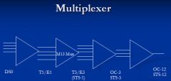
As T1 through T3 became accepted transmission rates, a standard called the North American Digital Hierarchy was developed.
Bit stuffing in the North American Digital Hierarchy is one of the reasons that individual 64 Kbps channels cannot be accessed within a higher rate bit stream without demultiplexing down to the channel level. This means that each time you need to monitor, add, or drop a 64 Kbps channel in a higher rate bit stream in the North American Digital Hierarchy, you must use hardware that performs the multiplex-demultiplex functions. This hardware adds to system cost. On the receiving end of the output bit stream, a demultiplexer must remove the stuffed bits and separate the interleaved bit streams. To make this possible, the multiplexer adds control bits to the high-speed signal to indicate the presence or absence of stuffed bits. Other non-information bits are added to the output bit stream, further increasing the output rate beyond the product of number of channels times the input bit rate. These bits are used for frame synchronization, parity checks, and maintenance communication. While bit stuffing solves the problem of signals coming from sources with different clock rates, it prevents recovery of lower-level signals from a high- speed bit stream without demultiplexing. The lack of this ability, known as add-drop multiplexing, means that additional multiplexing hardware is required anytime access to the lower-speed signal is required. This additional hardware adds to the cost of multiplexing, particularly as higher data rates are used. |
|
|
|
On an OC12 fiber between Chicago and New York.
How many telephone can I have on this circuit? |
OC-12
OC-12 = 4 X OC-3 OC-3 = 3 X T3 T3 = 28 X T1' T1 = 24 DS0's 24X28X3X4= 8064 |
|
|
|
What is the standard for Speech Quality?
|
Mean Opinion Score (MOS) – how is the audio quality of the voice sound?
ITU-T P.800 the standard – subjective measurement ITU-T P.862 –perceptual evaluation of speech quality (a tool-based) ITU-T G.107 – R-factor measurement (calculated) MOS Value = 1-5, 5 is excellent Toll quality: 4 or better |
|
|
|
ITU-T P.862 PESQ Measure second approach to MOS
|
Uses a sophiticated algorithm to comare two audio files. The origian file and a file transmitted over the network
|
|
|
|
What is the goal of MOS
|
Able to reach toll quality or a score of at least 4
|
|
|
|
The third MOS approach (ITU-T G.107 R Factor) is a calculation using the following
|
uses network performance where the major components are delay and also signal to noise ratio
|
|
|
|
CODEC VS MOS
|
|
|
|
|
What are the four major factos affecting VoIP quality
|
Delay, Jitter, Packet Loss, Codec schemes
|
|
|
|
What are the types of delay and what is the acceptable delay
|
Delay
Transmission delay Network device delay Endpoint delay Must be less than 150 ms for acceptable voice communication |
|
|
|
What are the type of jitter?
|
Jitter
Variation in delay Jitter buffer => delay |
|
|
|
When the delay is over 30ms you will be able to distinguish echo. What is done to address echo
|
Most devices now have echo cancellation to handle delay above 30ms
|
|
|
|
How packet loss is acceptable?
|
1-2% without experiencing quality degradation
|
|
|
|
Jitter
|
Jitter
Variation in delay Jitter buffer => delay |
|
|
|
What is the delay caused by Codec schemes
|
In the process of digitization there you must first obtain a sample. However, you wait to have enough data to perform the sample.
Once you have enough voice in order to perfrom the sampling. This interval is the delay. Depending on the Codec the delay may be small or it can be up to 30 ms |
|
|
|
The key factor affecting voice quality is
|
delay. All delays together must be less than 150ms
|
|
|
|
What are the components of delay
|
Transmission Delay
Solely based on the distance between endpoints Delay in Network Devices VoIP Endpoint Delay IP sampling rate (not the same as codec) 10 ms sampling rate => 20 ms delay (one way) Codec algorithmic delay G.711 << 1 ms G.723.1 ≈ 37.5 ms |
|
|
|
What are the three types of speech codecs?
|
3 basic types of codecs
Waveform codecs Source codecs (vocoders) Hybrid codecs |
|
|
|
What are the characteristicos of waveform codec
|
Incoming signal is sampled without any thought to how the analog signal was generated
They do NOT take into account characteristics of human speech in a given language Relatively simple, but need more bandwidth to provide accurate/good digital representation; they generally perform poorly at lower bandwidths Simplicity also means they impose very little algorithmic delay, which is good for voice (a delay-sensitive application) |
|
|
|
What are the characteristics of Source codecs?
|
Source – attempt to match incoming signal to a mathematical model of how the signal was produced (e.g., speech versus car engine sounds)
Use of linear-predictive filter to model vocal tract Both transmitter and receiver have this model built in At lower bit rates, the speech output can sound synthetic; adequate for military communications, but not acceptable for “toll quality voice” |
|
|
|
What are the characteristics of the hybrid approach to voice codecs
|
Hybrid – capitalize on the benefits of Waveform and Source
Get best quality at lower bit rates |
|
|
|
What are the characteristics of the G.711 codec?
|
most common today
a waveform codec if uniform quantization were used, it would take 12 bits/sample, leading to a bit rate of 96 kbps; Non-uniform quantization gets the same results with 8 bits/sample (64k bps) a.k.a. Pulse Code Modulation (PCM) Very good MOS (4.3 foundation for DS0 – 64 kbps two PCM variants -law – Used in North America and Japan, slightly skewed to be “friendlier” to lower signal levels A-law – used in Europe and the rest of the world and international routes Both provide good quality PCM sends each sample independently across the network |
|
|
|
What service does DPCM provide?
|
DPCM, Differential PCM
Only transmit the difference between the predicated value and the actual value Voice changes relatively slowly It is possible to predict the value of a sample base on the values of previous samples The receiver perform the same prediction The simplest form No prediction No algorithmic delay Based on the fact that the voice changes relatively slowly from sample to the next |
|
|
|
What service does ADPCM provide?
|
Adaptive Differential PCM (ADPCM)
Waveform codec Voice changes slowly – take advantage of this phenomenon The delta (∆) between sample N and N+1 is sent it is differential. S(n) + ∆(n, n+1) => S(n+1) Error between sample and actual value can be estimated and sent it is Adaptive. S(n) + Error(actual, prediction) => S(n+1) G.721, G.726; G.726 at 32kbps can provide MOS of 4.0 (toll quality) Commonly used on the toll network |
|
|
|
Hybrid Codec approach
|
Analysis-by-Synthesis (AbS) Codec (I)
Hybrid codec G.728 LD-CELP Low-Delay Codebook Excited Linear Predictive A codebook of “known points” from human speech is constructed, and the algorithm matches the samples to the codepoints and sends them along with other relevant info (“excitation parameters”) Lower bandwidth (16kbps) with good MOS (3.9) |
|
|
|
Analysis-by-Synthesis (AbS) Codec (II)
|
Hybrid codec
G.723.1 ACELP Algebraic CELP VERY low b/w: 3.8 MOS at 6.3kbps or 5.3kbps Disadvantage: introduces delay of approx. 37.5 ms at one end Support of silence suppression via Silence Insertion Description (SID) frames 4 octets and consumes only 1K bps => to indicate silence |
|
|
|
Analysis-by-Synthesis (AbS) Codec (III)
|
G.729
Relatively complex, algorithmic delay of 15 ms, but better than G.723.1 G.729A – simplification of G.729 Simplification of G.729, also has 15 ms delay 8kbps, MOS of 3.7 G.729B (coupled with G.729 or G.729A) Supports voice activity detection (VAD), discontinuous transmission (DTX), and comfort noise generation (CNG) CNG uses SID frames to simulate background noise based on different noise levels |
|
|
|
Analysis-by-Synthesis (AbS) Codec (III)
|
The result of receiving total silence, especially for a prolonged period, has a number of unwanted effects on the listener, including the following:
1. the listener may believe that the transmission has been lost, and therefore hang up prematurely. 2. the speech may sound "choppy" (see noise gate) and difficult to understand. 3. the sudden change in sound level can be jarring to the listener. |
|
|
|
Important Characteristics of Codecs
|
Audio bandwidth (higher is better)
• Data rate or bit rate (how many bits per second, fewer is better) • Audio quality loss (how much does it degrade the audio, lower is better) • Kind of audio (does it only work with speech, or with anything?) • Processing power required (less is better) • Processor memory required (less is better) • Openly available to vendors? (“yes” is essential) • Inserted delay (audio latency caused by the algorithm, less is better) • Resilience (how insensitive to lost or corrupted packets, more is better) • ITU standards-based (standardized by the International Telecommunications Union - “yes” is better) |
|
|
|
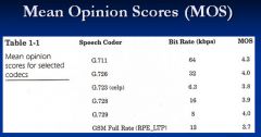
Data rate comparison for codecs
|
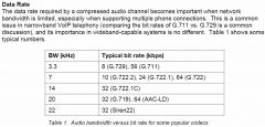
One thing we see here is that the typical bit rates don't necessarily rise with rising audio bandwidth;
the bit rate has as much to do with the codec chosen as with the bandwidth. The reasons for this are twofold: audio contains most of its information in the lower frequencies, so there's less information to be coded and sent in the higher frequencies, and the human ear is less sensitive to inaccuracies at the higher frequencies, so a compression algorithm can be a little less precise without being noticed. |
|
|
|
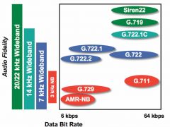
bandwidth vs bit rate
|
|
|
|
|
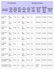
codec comparison
|
|
|
|
|
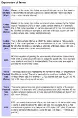
explanation of terms
|
|
|
|
|
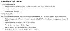
bandwidth calculation formulas
|
|
|
|
|
How do you decide which codec to use?
|
Test them!
To see if you get good quality. You must also measure the quality? Use common sense Digital Signal Processor (DSP) cost is a factor, too Largely going down, making more complex algorithms a reality DSP used to be an important factor, but with the advancement of chip technology this is less of an issue Hard to gain performance improvements in networks based on DS0, why? There's no free lunch. The more sample you take the better the quality, however this also increases the delay |
|
|
|
What are the two types of signaling
|
Dial path and DTMF
|
|
|
|
What type of signaling is DTMF
|
analog
|
|
|
|
What is the purpose of DTMF signaling?
|
To send digits
|
|
|
|
Each button sends
|
two tones
|
|
|
|
How do we encode the DDTMF signal into the digital signal?
|
???
|
|
|
|
The codecs need to handle the human voice and the other signaling
|
Human speech is the data to be transmitted, but there is more to it. Need to send signaling info as well
Station signaling (to/from PSTN) is maintained in the 0-4 kHz spectrum. Dial tone – do we really need it? Dual-Tone Multi-Frequency (DTMF) tones to signal numbers dialed and to access features (e.g., v-mail) Fax tones fit within the band Busy tone and fast busy (?) Low-rate codecs can’t always accurately represent these tones Plus, we’re used to hearing them, even though they might not be necessary in an all-digital context |
|
|
|
What is a fast busy?
|
More in the legacy environment. Means all circuits are busy. Now announcements are used for this purpose.
|
|
|
|
How we handle singaling all the frequencies in addition to human voice?
|
DTMF signals are sent immediately to CO.
However with IP phones this all handled by the IP phone We can use out-of-band signaling. Ways to handle these tones Use an external signaling system – out-of-band signaling This is ok for call setup/teardown, but not useful in the middle of the call – could be a problem Encode the tones differently from the speech Send in an IP packet with an appropriate identifier – “This is not speech, it’s signaling” Or, use a dynamic payload type just for the signaling Either way, the tones are provided to the local user as a “comfort tone”, but is carried across the network in a different way |
|
|
|
Summary
|
Analog Voice => Digital Signal
**Cost/Multiplexing Quality/Noise Resistance Nyquist Theorem Foundation of all digital communication. All anlog singals need to be digitized first Codec and Voice codec (what is the difference?) Different codec have different bandwidth requirements and give different voice quality Three approaches to MOS 1) Standard is subjective, where we observations from eight femals and eight males 2) Emulation. Requires a sophisticated tool 3)Calculation. VEry easy but very often is incorrect Different voice codecs: Trade off between bandwidth and voice quality Challenges in supporting station signaling |
|
|
|
What are five examples of analog signals?
|
Dial-tone
DTMF Busy Tone Fast Busy Fax Tone |
|
|
|
What is a long distance call?
|
A call from lata to another
After 1996 long distance calls must be handled by IEC |
|