![]()
![]()
![]()
Use LEFT and RIGHT arrow keys to navigate between flashcards;
Use UP and DOWN arrow keys to flip the card;
H to show hint;
A reads text to speech;
31 Cards in this Set
- Front
- Back
|
What is hold time |
Minimum amount of time after the clocks active edge wich data must be stable |
|
|
Setup time |
Minimum amount of time before the clocks active edge that data must be stable for it to be latched |
|
|
Using nand gates draw logic circuit of sr flip flop explain how it can store binary bit |

We can store binary when we set s-r to 1 |
|
|
Using nor gates draw circuit of sr flip flop and explain how can store binary |
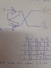
Can store binary when s,r are equal to 0 |
|
|
Draw logic symbol and truth table for jk flip flop |

|
|
|
Explain advantages of dtype when compared to sr flip flop |
In a high noise enviroment dtype is better because an sr flip flop samples continuously so noise will propergate through but a dtype has shorter sampling and noise will only just come through when its high. In a high noise enviroment dtype is better because an sr flip flop samples continuously so noise will propergate through but a dtype has shorter sampling and noise will only just come through when its high. |
|
|
Explain how dtype flip flop can store binary |
When the clock is low no change occurs thus storing Q |
|
|
Draw mod 16 asynchronus up counter |

|
|
|
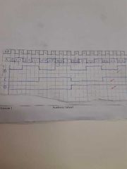
Mod 16 asynchronous timming diagram |
|
|
|
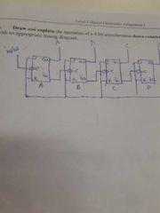
4 bit asynchronous down counter |
|
|
|
4 bit asynchronous down counter timming diagram |

|
|
|
Circuit diagram for mod 8 counter |

|
|
|
Timing diagram for mod 8 counter |

|
|
|
Draw circuit diagram of dtype flip flop |

|
|
|
Explain operation of synchronus up counter |
All the flip flop are comtolled by a master clock all the toggle inputs are connected to the count input wich can be a clock or any variable frequency signal. It counts from 0-15 mod 16 |
|
|
Explain how a BCD counter can be used to count from 0-99 |
We use a 2 seven segment displays each display is supported by its own 4 bit up BCD counter |
|
|
State advantages and disadvantages of synchronous counter over asynchronous counter. |
Asynchronous: advantage- simple construction Disadvantage: propergation delay/low speed Synchronus counter: ADV- high speed Disadvantage- complicated construction |
|
|
State difference between parallel and serial transfer |

|
|
|
Explain diffrence between level triggering and edge triggering |
Level triggering: do operation only when trigger is at a particular level Edge triggering: do pperation only when trigger is at a particular edge |
|
|
Explain diffrence beetween synchronous and asynchronous data transfer |
Asynchronous: transfer there is no common clock In synchronous data transfer is has a master clock used for data transfer |
|
|
Circuit diagram for monostable multivibrator |

|
|
|
Explain operation of monostable multivibrator |
When trigger input is slightly less than vcc/3 the lower comparator resets flip flop cuts off transistor wich allows capacitor to charge once capacitor is higher that 2/3 vcc upper comparator sets flip flop soon as q high it turns on transistor to discharge capacitor . |
|
|
Draw circuit diagram for astable multivibrator |

|
|
|
Explain oppertion of 555 astable multivibrator |
If Q=1 vbe=on c1=not charging cm1 output=0 cm2 output =1 When Q= 0 vbe=off c1=charging if vcc=15v when c1=5.1v cm2 output=0 once c1=2/3 vcc cm1output=1 |
|
|
Markspace ratio |
The ratio of time spent at highoutput to time spent at low output |
|
|
Duty cycle |
The percebtage of output at high state in one cycle. Th/th+tl |
|
|
Frequency |
The ammount of cyclez completed during one unit of time (s) |
|
|
Formular for charging time constant and discharge time fo astable multivibrator |
Charging= (RA+RB)c Discharging= RBc |
|
|
An astable 555 timer has Ra=2k ohms Rb=4kohms and c=100ųF |
F= 1.44/(ra+2rb)c D=RA+RB/RA+2RB ×100% |
|
|
Explain application of monostable multivibrator. |
Snooze button- when pushed will stay in high state for pre determind time snoozing alarm untill goes back to low state where will buzz again |
|
|
Explain one application of a astable multivibrator |
Every computing system. Clock is used to synchronize devices in a computer system |