![]()
![]()
![]()
Use LEFT and RIGHT arrow keys to navigate between flashcards;
Use UP and DOWN arrow keys to flip the card;
H to show hint;
A reads text to speech;
41 Cards in this Set
- Front
- Back
|
Microphone cables |
can run for several meters without booster amplifiers (ifbalanced twisted pairs). |
|
|
Line level cables |
be balanced to reject EM noise. |
|
|
Speaker cables |
Carry currents that are high enough to not need balancing & should be as thick / short as possible |
|
|
Stereo system cables |
should be of equal length |
|
|
Capacitance: |
long lengths of parallel cable act as plates in a capacitor |
|
|
Inductance: |
improperly coiled cables can induce current into each other,causing noise. |
|
|
Cable Laying: |
end and return cables shielded / separate from each other (capacitance/inductance between send and return = feedback). Do not place HT (high tension power or lighting) cables near audio leads as thiscauses noise. |
|
|
Stage Box |
containing XLR connections for ‘mic’ and DI signals Collects ‘mic’ / DI signals and feeds them into a multicore cable . Many stage boxes may be used at once on stage (one specifically for drummicrophones, etc.) |
|
|
Microphone Splitter Box |
Splits stage mic/DI signals into two or more copies (FOH / monitor consoles) Active - FOH console must not be fed via transformer (phantom power wouldbe blocked). Active – May derive power from console (for self-operation). May be passive (simple parallel split) or active (transformers used preventingdirect electrical connections from causing earth loops). |
|
|
Multicore / Snake |
Many cables (signals) housed within one larger cable. EDAC connections are the most common (allowing for easy connection). |
|
|
Live Sound Graphic EQ |
Used to tune/condition the signal being sent to speakers (usually 31bands typeused). Graphic Equalisers allow maximisation of level before feedback. FOH - Used to ‘tune’ the room slightly by attenuating room modes, etc.Foldback speakers - Used to prevent feedback / tune speakers to a musician’srequirements |
|
|
Live Sound Feedback Buster |
An automatic, dynamic graphic EQ.• Feedback has a very distinctive envelope that is recognised and attenuated by the feedback buster |
|
|
Limiters |
Used to protect the crossover, amps and speakers from extreme transients thatmight occur. |
|
|
Crossover |
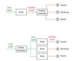
A set of filters splitting the frequency range into separate bands destined forspecific types of speaker drivers. |
|
|
Amplifiers |
should be placed as close to speakers as possible i.e. long speakercables affect efficiency / increase impedance. |
|
|
Bridging Stereo Amplifiers |
Most amps have a mono/stereo or bridge/normal switch.One O/P (usually right) is polarity reversed (when amp is set on ‘bridged’ mode)O/P is taken from the positive terminals of the two channelsThe RMS voltage is effectively doubled which would relate to a 4X increase inpower. The electrical components usually cannot deal with this increase inpower so the impedance of the amp is doubled which relates to only a‘controlled’ power increase to double the normal power. |
|
|
Power Rating |
Continuous power (long term average)Tested with pink noise typical program material Peak powerMaximum, instantaneous, short-term power handling RMS powerAverage sine-wave producing power that can be handled over long periodsTested / measured using a sine inpute.g. A 300 Watt ‘RMS’ amplifier would be able to produce a 100 Watt sine-wave on the load. |
|
|
Power Matching |
As a rule of thumb, amplifiers should have power rating equal to at least twice theIEC continuous power rating of the speakers. |
|
|
Damping Factor |
The damping factor describes the ability of the amplifier to control the movementof the driver’s cone. It is calculated as a ratio of load impedance over outputimpedance.The higher the damping factor the higher the fidelity. |
|
|
Slew Rate |

Measure of an amp’s ability to track an input transient and reproduce it at theoutput.Measured in ‘volts per microsecond’ V/μsImportant during high amplification levels when it is harder for the amp toreproduce the transients accurately. Good Slew Rates: • amps up to 100W (continuous) = 10V/μs• amps over 200W (continuous) = 30V/μs V= max peak voltage |
|
|
Clipping |
Occurs when an amplifier attempts to reproduce levels over those for which it isdesigned.When a sine wave is driven through an amp and its level is increased to clipping itwill resemble a square wave. This is due to the fact that harmonics were added(harmonic distortion) which results in a higher voltage resulting in a 3dB boost inlevel over a sine wave at max level. |
|
|
Amplifier Protection Mechanisms |
Protect the amp from short circuits at its outputs (from very low Z or incorrectconnections)• Protect the amp from overheating (e.g. it will automatically switch off or a fusewill blow) • Protect the speaker from on/off transients. |
|
|
Speakers |
Speakers may contain different drivers for different frequencies:2 Way (HF and LF drivers)3 Way (HF, MF and LF drivers) |
|
|
Bi-amping |
Different speakers / drivers are powered by different amplifiers through the use ofan active crossover network. |
|
|
Speaker Placement |
Spaced speaker systems may cause comb filtering (mainly at LF).‘Cluster’ of speakers radiate the sound outwards with less interference and combfiltering (better clarity/definition) |
|
|
= HF speakers: |
Very directional Must be aimed at audience Coverage angles to determine placement Placed high up above the stage If the audience is very large then ‘long throw’ speakers can project HF (andsometimes MF) to the rear audience using directional horns |
|
|
LF speakers: |
Less directional Do not need to be placed high up / may be placed under or along-side thestage (adequate LF radiation) If placed in a corner then the 3, 6 or 9 dB SPL increases can be used |
|
|
Delay Towers |
If the audience is too large and the sound levels at the back are too low, extraspeakers may be used for reinforcement (delay distribution system).‘Delay towers’ provide delayed sound O/P to the audience in order to preservelocalisation and maintain visual and audible sync. |
|
|
Amount of delay: |
Time taken for sound to travel from FOH to Delay tower + Haasamount.Haas delay added so that the audience will still perceive the sound as comingfrom the FOH (this allows the delay tower’s level to be up to 10dB louder withoutaffecting localisation). |
|
|
Other factors will affect the sound’s movement: |
Live Sound Air temperature: Lower temperatures will slow the sound down (use longerdelay times) Wind |
|
|
Impedance matching |
The amount of power drawn from an amp by a driver is proportional to itsimpedance. |
|
|
Impedance matching series |
Series: ZT =Z1 +Z2 +Z3 +... Voltage is split but current is the same for all speakers Disadvantage of series speaker configuration: If one speaker is faulty, all the other speakers are affected More interaction between speakers could cause distortion The damping factor as seen by each individual speaker is degraded - eachspeaker ‘sees’ more source Z) |
|
|
Impedance matching Parallel |
Parallel: 1/ZT = 1/Z1 + 1/Z2 + 1/Z3.... Current is split but voltage is the same across all speakers Advantages of parallel array: If one speaker breaks down the others are not affectedDamping factor is not adversely affected |
|
|
FOH Console |
Any type of console may be usedMain speakers fed by stereo bus (not a separate monitor section)High voltage lines may be needed to feed FOH (voltage stepped up /transmitted / stepped down) Required Features: Channels have on/off switches (prevent unwanted signals from feedingFOH speakers) Many fader / mute groups (VCA groups) Many auxiliaries Gates (gate as much as possible) PFL soloing L-C-R pan assign |
|
|
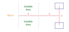
Front/Back Placement of FOH Console |
- Between1/3 and1/2 the length of hall from stage - Not closer than the distance between the speakers and not further thantwice the distance between the speakers. |
|
|
Left/Right placement of the FOH Console |
On the middle line to prevent comb-filtering (may only benefit peoplestanding on the middle line) |
|
|
Monitor Console |
Matrix consoles are preferred (multiple mixes)Auxiliar feeds may be used on all types of consoles to create different mixes |
|
|
Powered Mixers |
A mixer with built-in power ampOutputs must be at speaker levelsGood for small venues (pubs) but can be limiting in size, power andfacilities |
|
|
Digital Consoles |
Digital consoles are extremely efficient as they offer ‘recall’ functions‘Recall’ combined with IEM makes monitor mixing extremely easy |
|
|
Tips for Mixing FOH |
Live Sound Do FOH mix before monitor mix (specially in small venues)Set vocal levels higher than in a ‘studio mix’ (treat songs like you’ve neverheard them)Don’t be afraid of using ‘drastic’ EQFilters (cut mids) may be used to create space on pre-recorded (pre-mixed /samples / etc.) material |
|
|
Tips for Monitor Mixing |
Remember always to use pre-fader ‘auxes’Take advantage of rear rejection by pointing a cardioid ‘mic’ to the singer’smouth (perpendicular to wedge)Avoid putting low end through to the wedgesWhen using IEM: Have a pre-made mix ready Small changes are effective! |