![]()
![]()
![]()
Use LEFT and RIGHT arrow keys to navigate between flashcards;
Use UP and DOWN arrow keys to flip the card;
H to show hint;
A reads text to speech;
28 Cards in this Set
- Front
- Back
|
Explain why it is only electrons that move when static electric charges are produced. |
The positive charges, protons, are fixed in the nucleus. |
|
|
In an experiment, two pieces of the same type of plastic were rubbed separately by two different students using the same type of cloth.
If the two pieces of plastic are brought together will they attract each other or repel each other? Explain why. |
They will repel because they will have the same charge. |
|
|
Lightning is an example of static electricity discharging between clouds and the ground. When lightning strikes,a large current flows for a very short time and this can damage buildings. Explain how a lightning conductor can protect a building. |
The lightning conductor provides a very low resistance route for the charge to flow through, so the current mostly flows through the lightning conductor and not the building. |
|
|
Damp air conducts electricity much more easily than dry air. Would it be easier to do static electricity experiments on a dry or damp day? Explain your answer. |
A dry day because the charge will not conduct away through the damp air. |
|
|
Draw a parallel circuit containing a cell and two 100 Ω resistors in parallel. If the cell has a p.d.of 4 V, what is the current through each resistor? |
Voltage across both resistors is 4 V; resistance of both is 100 Ω. I = V/R, so current = 4 V/100 Ω = 0.04 A (or 40 mA). |
|
|
If a current of 3 A passes through alight bulb that has 5 V across it, calculate the following: (a) the power of the light bulb (b) the resistance of the light bulb (c) If only 2.5 V was put across the light bulb, what do you think the current would be? Explain your answer. |
(a) Power = I× V= 3 × 5 = 15 W (b) Resistance = V/I = 5/3 = 1.7 Ω. (c) If the voltage halves, the current will be more than half of previous value (less current means less heat so the resistance is also reduced). |
|
|
Two resistors are in series and the p.d.across them both together is 9 volts. One resistor has a resistance of 800 Ω; the other has a resistance of 400 Ω. Calculate the following: (a) the total resistance of the resistors (b) the current flowing through the resistors (c) the p.d. across each resistor. |
(a) 1200 Ω. (b) Current = V/R = 9/1200 = 0.0075 A or 7.5 mA. (c) P.d. = 6 V across the 800 Ω resistor and 3 V across the 400 Ω resistor. |
|
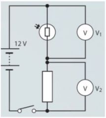
Refer to the figure. (a) Describe what will happen to the resistance of the LDR as it gets darker. (b) What will happen to the LDR’s share of the voltage as it gets darker? Explain why. (c) If the LDR had a resistance five times that of the resistor, what would V1 and V2 be? |
(a) The LDR’s resistance will get larger. (b) It will take a larger share of the voltage because its resistance increases. (c) V1 = 10 V; V2 = 2 V. |
|
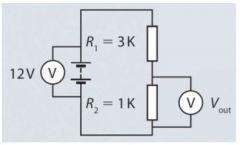
Calculate the current in the circuit in the figure. What is the value of the p.d. labelled Vout? |
Current = 12/4000 = 0.003 A or 3 mA. Vout = (12 × 1000) / 4000 = 3 V. |
|
|
An a.c. current is applied to a diode and a bulb in series. (a) Describe the way that the bulb will light up. (b) Sketch a graph of current against time for the current in the bulb. |
(a) The bulb will be dimmer than if the diode was not there and will flash bright and dim 50 times a second. (b) Correctly drawn graph of current against time for bulb. |
|
|
Explain why a cell is a better option for a small torch than using mains electricity. |
A cell is far more portable than mains electricity. |
|
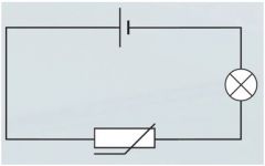
Describe the function of the circuit in the figure. Explain what happens to the current in the circuit and the brightness of the bulb as the temperature changes. |
The thermistor’s resistance falls as temperature rises: this acts to increase the current as the temperature rises, so the bulb will get brighter with increasing temperature. |
|
|
A student built a series circuit with two light-emitting diodes in it. She made sure that they pointed in opposite directions in the circuit. She said ‘If I have one diode pointing in each direction, then at least one of them will light up.’ Explain why this reasoningis wrong. |
If they are pointing in opposite directions, one of them will stop current flowing and, as they are in a series circuit, if the current stops in one place then it stops in all places. |
|

An LDR is to be placed in series with a fixed-value resistor of value 500 Ω.If the LDR and resistor have a p.d. of 9 V across them. The LDR’s resistance changes during the day. What will be the voltage across the LDR at: (a) 10am? (b) 4pm? (c) 8pm? |
(a) 1.6 V. (b) 1.4 V. (c) 4.7 V. |
|
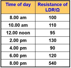
Looking at the values for the resistance of the LDR in the previous question, can you suggest a reason why the resistance is higher at 2 pm than at 4 pm?
|
Possibly a cloud was in front of the sun making it a little darker. |
|
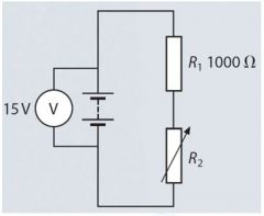
The figure shows a circuit with two resistors in series. (a) Describe what will happen to the current that flows in this circuit as the variable resistor (R2) changes from 0 Ωto its maximum value of 5000 Ω. Include maximum and minimum values for the current. Show your working. (b) What will be the maximum and minimum values for the p.d. across the 1000 Ω resistor as R2 is changed? (c) The variable resistor is adjusted so that the current through the circuit is 0.02 mA. What is the new value of the resistance R2? (d) The variable resistor is adjusted until the p.d. across the fixed resistor is 3.6 V. What is the value of R2 now? |
(a) As the resistance increases the current decreases. Maximum resistance is 6000 Ω (1000 + 5000). I = V/R = 15/6000= 2.5 mA minimum. Minimum resistance is 1000 Ω (no resistance from variable resistor) I = V/R =15/1000 = 15 mA maximum. (b) 15 V maximum / 2.5 V minimum. (c) 749 000 W. (d) 3167 W. |
|
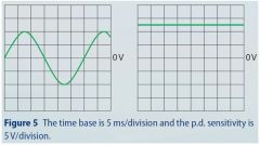
Look at the figure. Describe the p.d.s represented in as much detail as possible. |
The left trace shows an a.c. voltage. Peak voltage is 10 V. Period is 30 ms. Frequency is 33 Hz. The right trace is d.c. and the voltage is 12.5 V. |
|
|
A student is investigating the resistance of a series of wires made from different materials. Describe what actions he should take to ensure that his experiment is a fair test. |
The length and thickness of each wire should be the same. They should be kept at a constant temperature and the voltages used should be the same for each one. |
|
|
Apiece of resistance wire was used to make a component with a resistance of 1.75Ω. The label on the reel of wire noted that the wire had a resistance of 4 Ω per metre. What length of wire would be needed? |
About 44 cm. |
|
|
A student placed a voltmeter in series with a light bulb, rather than in parallel with it. Explain why the voltmeter would not work like this. |
A voltmeter has a very high resistance, so if it was placed in series with other components it would make the flow of current very small. |
|
|
A digital ammeter reads ‘4.23’. If the meter is set to measure up to 10 mA, what is this current in amps? |
0.004 23 A. |
|
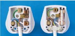
Look at the two images of three-pin plugs. For each one describe the fault in the wiring. |
On the left there is no fuse and the cable grip is missing. On the right the blue and red cables are connected the wrong way round and there is no screw in the earth lead. |
|
|
A 300 W grinder is powered by UK mains electricity. What size fuse would it need: 1 A, 3 A or 13 A? Explain your answer. |
Power = I × V, so for a device running on mains electricity, 300 = I × 230 therefore I = 300/230 = 1.3 A. Grinder needs a 3 A fuse. |
|
|
Describe how an earth wire and a fuse work together to protect the user from an electrical fault in a coffee grinder and explain why using too high a fuse rating in this device could be dangerous. |
If the live wire becomes disconnected in the coffee grinder and touches the metal casing, the earth wire provides a very low resistance path for the electric current to flow down. This increases the current to a value higher than the rating of the fuse. The high current heats up the wire inside the fuse and melts it. This disconnects the grinder from the mains live supply and the grinder will not electrocute somebody touching it. If a 13 A fuse were used, an electrical fault could cause a current of 10 A to flow but it would not blow the fuse. A current of 10 A could be dangerous. |
|
|
A student was investigating the flow of current in very thin fuse wires. Describe what happened to the current, and the wire, as he slowly increased the voltage across the wire. |
As the voltage increased, so would the current. As the current increased, the wire would get hot and eventually melt, stopping the current flow. |
|
|
Safety advice recommends that people should not use too many appliances from the same socket. Explain why this is dangerous. |
If several high-power appliances are used, the current flowing in the main circuit can get too large for the mains wire buried in the wall, which can overheat and cause a fire. |
|
|
Describe how an RCCB circuit breaker can help prevent injury in the garden. |
An RCCB detects the difference between current flowing in the live and neutral wires. [Some faults with electrical equipment do not blow a normal fuse but will cause an RCCB to trip and disconnect the appliance from the mains.] |
|
|
A hand dryer has two electrical functions. It has a heating element and a motor that drives a fan to move air. The heating element is a coil of wire that warms up when electric current flows through it. (a) If the hand dryer has a power of 2300 W, what current will flow through the heating element if the voltage is 230 V? (b) Some modern hand dryers use very low-power heaters, but much more powerful motors, so that the air speed is much higher and knocks the water off your hands. Explain why will this be a cheaper option to run than hand dryers that use slower, hotter air? |
(a) 10 A. (b) The reduction in heater power is much greater than the increase in motor power, so less power is used. OR Because the dryer knocks the water off, there is less water that needs to be evaporated, so less energy is used. |