![]()
![]()
![]()
Use LEFT and RIGHT arrow keys to navigate between flashcards;
Use UP and DOWN arrow keys to flip the card;
H to show hint;
A reads text to speech;
34 Cards in this Set
- Front
- Back
- 3rd side (hint)
|
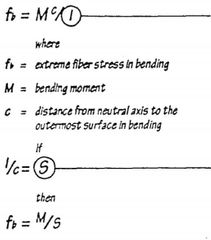
A formula defining the relationship between bending moment, bending stress and the cross sectional properties of a beam. Bending stress is directly proportional to bending moment and inversely proportional to the moment of inertia of a beam section. |
FLEXURE FORMULA |
|
|
|
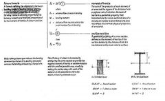
The buckling of a structural member unduced by compressive stresses acting on a slender portion insufficiently rigid in lateral direction. |
LATERAL BUCKLING |
|
|
|
The tensile and compressive stresses resulting from the interaction of bending and shear stresses at a cross section of a beam. |
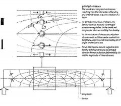
PRINCIPAL STRESSES |
|
|
|
Lines depictIng the direction but not the magnitude of the principal stresses in a beam. |
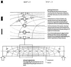
STRESS TRAJECTORIES |
|
|
|
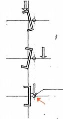
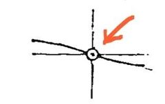
The point in the crosssectional plane of a structural member through which a transverse load must pass in order to prevent tortion or twising of the member about a logitudinal axis. |
SHEAR CENTER |
|
|
|
A graphic representation of the variation inmagnitude of the external shears present in a structure for a given set of transverse loads and support conditions. |
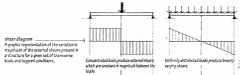
SHEAR DIAGRAM |
|
|
|
A graphic representation of the variation in magnitude of bending moments present in a structure for a given set of transverse loads and support conditions. The overall deflected shape of a structure subject to bending can often be inferred from the shape of this. |
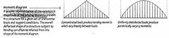
MOMENT DIAGRAM |
|
|
|
A beam resting on simple support at both ends, which are free to rotate and have no moment resistance. As with any statically determine structure, the values of all reactions, shears and moments for this beam are independent of its cross sectional shape and material. |
SIMPLE BEAM |
|
|
|
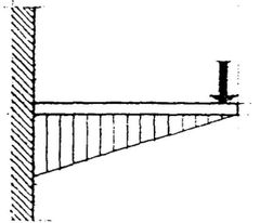
A projecting beam supported at only one fixed end. |
CANTILEVER BEAM |
|
|
|
A beam or other rigid structural member extending beyond a fulcrum and supported by a balancing member or a downward force between the fulcrum |
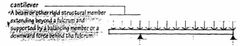
CANTILEVER |
|
|
|
_________ is the net resultant shear forces that acts vertically UPWARD on the left part of the structure being considered.
and
_________ is the net resultant shear forces that acts vertically DOWNWARD on the left part of the structure being considered. |

POSITIVE SHEAR
and
NEGATIVE SHEAR |
|
|
|
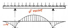
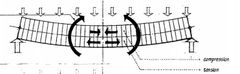
A bending moment that produces a CONCAVE curvature at a section of a structure. |
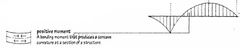
POSITIVE MOMENT |
|
|
|
A point a which a structure changes curvature from convex to concave or vice versa as it deflects under a transverse load: theoretically an internal hinge and therefore a point of zero moment. |
INFLECTION POINT |
|
|
|
A bending moment that produces a CONVEX curvature at a section of a structure. |
NEGATIVE MOMENT |
|
|
|
A part of the beam that is thickened or deepend to develop greater moment of resistance. The efficiency of a beam can be increased by shaping its length in response to the moment and shear values which typically vary along its longitudinal axis. |
HAUNCH |
|
|
|
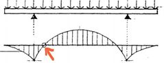
A simple beam supported by cantilevers of two adjoining spans with pinned construction joints at points of zero moment. Also called hung-spun. |
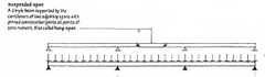
SUSPENDED-SPAN |
|
|
|
A beam extending over more than two supports in order to develop greater rigidity and smaller moments than a series of simple beams having similar spans and loading. Both fIxed-end and continuous beams are indeterminate structures for which the values of all reactions, shears, and moments are dependent not only on span and Ioading but also on cross-sectlonalshape and material. |
CONTINUOUS BEAM |
|
|
|
The distance between inflection points in the span fixed-end or continuous beam equivalent in nature to the actual length of 3 simply supported beams. |
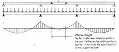
EFFECTIVE LENGTH |
|
|
|
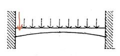
A beam having both ends restrained againts translation and rotation. The fixed ends transfer bending stresses. Increase the rigidity of the beam, and reduce its maximum deflection. |
FIXED-END BEAM |
|
|
|
A simple beam extending beyond one its supports. The overhang reduces the positive moment at midspan while developing a negative moment at the base of the cantilever over the support. |
OVERHANGING BEAM |
|
|
|
A simple beam extending beyond both of its supports. |
DOUBLE OVERHANGING BEAM |
|
|
|
A rigid structural member designed to carry and transfer transverse loads across space to supporting elements. |
BEAM |
|
|
|
The extent of space between two supports of a structure. Also, the structure so supported. |
SPAN |
|
|
|
The distance between the inner faces of the supports of a span. |
CLEAR SPAN |
|
|
|
The center-to-center distance between the supports of a span. |
EFFECTIVE SPAN |
|
|
|
An external moment tending to cause part of a structure to rotate or bend, equal to the algebraic sum of the moments about the nuetral axis of the section under consideration. |
BENDING MOMENT |
|
|
|
An internal moment equal and opposite to a bending moment, generated by a force couple to maintain equilibrium of the section being considered. |
RESISTING MOMENT |
|
|
|
The perpendicular distance a spanning member deviates from true course under transverse loading, increasing with load and span, and decreasing with an increase in moment of inertia of the section or modulus of elasticity of the material. |
DEFLECTION |
|
|
|
A slight convex curvature intentionally built into a beam, girder, or truss to compensate for an anticipated deflection. |
CAMBER |
|
|
|
An external shear or force at a cross section of a beam or other member subject to bending, equal to the algebraic sum of transverse forces on one side of the section. |
TRANSVERSE SHEAR |
|
|
|
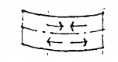
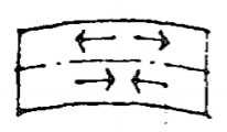
The shearing stress developed to prevent slippage along longitudinal planes of a beam under transverse loading, equal at any point to the vertical shearing stress at that point. Also called longitudinal sheraing stress. |
HORIZONTAL SHEARING STRESS |
|
|
|
An imaginary line passing through the centroid of the cross section of a beam or other member subject to bending, along which no bending stresses occur. |
NEUTRAL AXIS |
|
|
|
A combination of compressive and tension stresses developed at a cross section of structural member to resist a transverse force, having a maximum value at the surface furthest from neutral axis. |
BENDING STRESS |
|
|
|
The shearing stress developed along across section of a beam to resist transverse shear, having a maximum value at the neutral axis and decreasing nonlinearly toward the outer faces. |
VERTICAL SHEARING STRESS |
|