![]()
![]()
![]()
Use LEFT and RIGHT arrow keys to navigate between flashcards;
Use UP and DOWN arrow keys to flip the card;
H to show hint;
A reads text to speech;
5 Cards in this Set
- Front
- Back
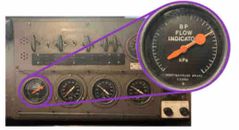
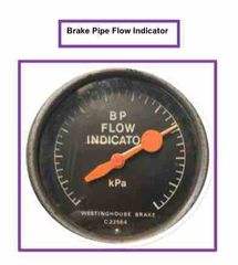
What is the function of both pointers on the flow meter gauge? |
White pointer - registers main reservoir pressure Orange pointer - connected to and is controlled by the action of the flow meter valve and responds to the airflow through the automatic brake valve to the brake pipe |
|
What does the flow meter and gauge indicate to the driver? |
To warn the driver if air is being lost from the brake pipe, it also indicates when the brake pipe is being recharged. The meter will move when main reservoir air is continuously being pumped into the brake pipe. |
|
|
In which positions of the automatic brake valve does the flow meter operate on No4 and 26L brake equipment? |
No4 brake equipment - CHARGING & RELEASE or RUNNING 26L brake equipment - ALL POSITIONS except EMERGENCY |
|
|
What is the indication given by the flow meter when brake pipe leakage occurs? |
Brake pipe leakage or any other cause of brake pipe pressure being reduced, will cause an increase in the flow rate of air through the venturi. This is indicated by the orange pointer rotating in an anti clockwise direction and fluctuating. Brake pipe leakage will cause an increase in the flow of air through the Venturi, which results in an audible warning in the form of rapid successive blows of air from the flow meter valve. |
|
|
What action would the driver take if the flow meter operates in running? |
On No4 if the train has divided: - leave the brake handle in the RUNNING position consistent with safety and in regard to the position of the rear portion of the train - otherwise, place the brake handle to the LAP position to bring the train to a stand On 26L if the train has divided: - leave the brake valve cut-off into the IN position consistent with safety and due regard to the position of the rear portion of the train - otherwise, place the brake valve cut-off valve to the OUT position and bring the train to a stand NB: failure to close the brake valve cut-off valve may result in an unintentional release of the train brake due to the brake pipe maintaining feature. * basically, determine if the train has divided. If it has divided, ensure the rear portion won’t run into the front portion. Once this has been established, bring the train to a stand. |