Reading...
![]()
Play button
![]()
Play button
![]()
Use LEFT and RIGHT arrow keys to navigate between flashcards;
Use UP and DOWN arrow keys to flip the card;
H to show hint;
A reads text to speech;
36 Cards in this Set
- Front
- Back
|
System Definition
|
Related Parts
Shared Functional Goal Complex Functionality |
|
|
Software and Systems Engineering Definition
|
Systematic approach
methods and Tools Finding Solution to problems Software Subset of Systems |
|
|
Life Cycle Processes - V-Model
|
Requirements Capture
Architecture Design Sub System Design Implementation Sub System testing Integration testing Verification and Validation |
|
|
Define the V-Model
|
Model of how system life cycle processes fit together
Abstract to refined general to Detailed |
|
|
Traceability
|
Documenting the change of a requirement from it's definition to its corresponding design and implementation element , to its test case
The evolution of a requirement from low to high level |
|
|
Definition and Types of Requirement
|
A service a system must provide
Functional - Qualitative and Descriptive Non-Functional - Quantitative and Measurable - Reliability, Response, Portability, Efficiency, Constraints User Requirements - Type of Functional |
|
|
Embedded Systems Definition
|
Systems with software based control
|
|
|
What is a good requirement?
|
Verifiable Attainable Clear Concise Unambiguous and Necessary
Identifies a Complete Set of Services |
|
|
How to find requirements?
|
Gather Information from Stakeholders - What and Why?
Usage Scenarios Problem Domain |
|
|
Sections of a requirements Documents
|
Glossary and Introduction
User Requirements Definition System Architecture System Requirements System Models Evolution and Appendices |
|
|
UML - Definition and Creator
SysML - Definition and Creator |
A graphical Modeling language for systems by OMG
Adaptation of UML - INCOSE |
|
|
Diagrams to include in a requirements document
|
UML Use Case
Block Definition Diagram Package Diagram Requirements Diagram Activity Diagram |
|
|
Use Case Diagram - Definition and Purpose
|
Tools to visualize user requirements
Use Cases - Shows Services Provided Actors - users of the services - Subsystems, Hardware, people, boundary systems etc |
|
|
Syntax for Textual and Visually Displaying Requirements in a SysML Requirements Diagram
|
Textually - Uniquely numbered, hierarchical and formal language
Visually - Text in rectangle boxes, arrows with relationship names |
|
|
Requirement Relationships
|
Derive Requirement
Namespace Containment Satisfy Copy Verify Refine - Comments Trace - Comments |
|
|
Context Model - Definition and Usage
|
Shows scope and boundary of a system
Define the flow of information to and from the system and the environment |
|
|
Activity Diagram
|
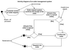
Shows information flow to and from
shows Information flow within system Shows control actions within the program Describes control flow from one example to another |
|
|
Use and reason for Object Oriented Methods
|
Reliability
Reusability Abstraction Modularization |
|
|
Definition of a Class and Object
|
Generic Structure for a set of elements with similar characteristics
Blueprint of the Object A specific instance of a class. Objects have data and behavior and are the building blocks of the system |
|
|
Encapsulation Definition
|
Combination of data and behavior (attributes and methods in a class)
|
|
|
Inheritance Definition
|
Subclass inherits data and behavior from class
Subclass may change/add more |
|
|
Class Relationships
|
Association
Navigation Aggregation Composition Inheritance Dependency |
|
|
Multiplicity Definition
|
Number of instances of each class in a relationship
|
|
|
Identifying Objects?
|
Nouns and Noun Phrases - Responsibilities of a System - Defining Information
|
|
|
SysML block diagrams
|
Similar to UML class diagrams - Difference being blocks represent software, hardware and subsystems
Standard ports - Request for Services Flow Ports - Data flow |
|
|
Sequence Diagrams
|
Shows object cooperation to provide use case functionality
Shows interactions involved in a use case |
|
|
State diagrams
|
Snapshot of an object during a specific instance in time
|
|
|
Module in OO
|
Class/Object or a method in a class
|
|
|
Cohesion - Definition and Types
|
The strength of the interdependency between the elements of a module
Coincidental (low) Logical Procedural Temporal Communicational Sequential Functional (high) Object Cohesion - Methods and Attributes Method Cohesion - private variables, program statements, private methods |
|
|
Coupling - Definition and Types
|
The strength and number of relationships between modules
Common (high) External Control Stamp Data Message (low) |
|
|
What happens upon instantiation ?
|
Memory allocated to hold object
Constructor is run Data is initialised |
|
|
Errors - Types of Failures
|
Fail Hard - System Stops
Fail Soft - Performance Declines Fail Safe - Failure Leaves system in a safe state |
|
|
Validation
|
Does the system meet the user needs?
|
|
|
Verification
|
Does each component meet its specification and is it error free?
|
|
|
Scenario Based Testing
|
Plan scenarios for each use case
Sequence Diagrams will help identify objects Set up tests from a user/actor perspective |
|
|
Approaches to testing
|
Input Stimulus
Measured Response Test Plan Strategic Testing |