![]()
![]()
![]()
Use LEFT and RIGHT arrow keys to navigate between flashcards;
Use UP and DOWN arrow keys to flip the card;
H to show hint;
A reads text to speech;
39 Cards in this Set
- Front
- Back
|
Induction |
A voltage can be produced by moving a conductor through a magnetic field or by moving a magnetic field pass a conductor a conductor ( Relative motion) |
|
|
Inductance property |
Inductance is the property of a circuit that opposes change in a circuit. Induction is the process by which a voltage is produced by an interaction of interaction of conductors and magnetic field. |
|
|
Mutual induction |
Neutral induction occurs when a change of current is one circuit causes a voltage to be induced in another circuit also called transformer action |
|
|
Single phase transformer construction |
A transformer is an alternate current device that transfers energy for one AC circuit to another AC circuit through the electromagnetic induction. At least 2 quails of wire wound on one common soft iron core, magnetic circuits links the 2 coils
|
|
|
Magnetic cct |
Is the transfer in Normally a complete path of low resistance material with no air gaps, the efficiency of Transformers ranges from 95 to 98 over a wide range of loads. |
|
|
Reluctance |
Is the opposition offered to the establishment of magnetic flux in a magnetic circuit.
- air has a high reluctance - iron has a low reluctance |
|
|
Soft iron core and changing magnetic flux |
Eddy currents and hysteresis can cause transformer losses. 2 reduced losses the core is made up of good of good magnetic quality such as silicone steel to reduce hysteresis. Laminating them with a thin coat of varnish which insulates them from one another decreases the amount of Eddy current that can flow in the core. |
|
|
3 basic types of Transformers |
- core - shell - h-type |
|
|
Core |
- highest leakage flocks - winding are wrapped around the core
|
|
|
Shell type |
- less leakage flux - core is wrapped around the winding |
|
|
H type |
- least amount of leakage flux - more core wrapped around the winding - Most efficient - Is usually used in high power distribution |
|
|
Efficiency |
There are virginities high 95% to 98% over a wide range of loads. They are not a 100% because copper losses in the windings as well as Eddy currents and hysteresis is lost in the core. |
|
|
Eddy current |
Are currents that are induced into the metal core which of course materials by the charging magnetic field as the ac produces a changing flux. They produce heat which is a power loss |
|
|
Hysteresis losses |
Are due to molecules friction caused by the reversal of the direction of current flow. Molecular rubbing together causes heat which is a power loss. |
|
|
Core losses |
Frequency of the source voltage, the higher the frequency is the greater the losses power losses due to hysteresis and Eddy currents are called core losses |
|
|
Rating and nameplates data |

|
|
|
More ratings and nameplate |
- frequency - temperature rise in C° - % impedance - type of insulating oil - serial number - type number - whether it is single-phase or three-phase |
|
|
Primary and secondary wine |
Winning that is connected to the input voltage in the winding where the magnetic flux originates is called primary winding.
Input windings connected to the energy source is called primary windings and the output is called secondary warnings |
|
|
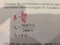
Transformer current rating formula |

|
|
|
Single-phase transformer |
Three functions - to step up the voltage of the cct - to step down the voltage of the cct - to isolate one cct from another |
|
|
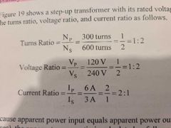
Step-up transformer |
The secondary transformer voltage is higher than the primary voltage. Use to increase voltage levels 2 transferred power over long distances. Primary is on input Secondary is on output |
|
|
Step down transformer |
The secondary transformer voltage is lower than the primary voltage used to which used to supply residential consumers is a step down transformer that lower the distribution line voltage to a lower level of consumer use. Primary on the input Secondary on the output |
|
|
Isolation transformer |
Isolates the conductors on the output side from ground. The secondary voltage is mot changed but is Isolated from the supply voltage through transformer action. Voltage load is equal having a 1:1 ratio |
|
|
Standard terminal identification |
High voltage terminal or leads to be identified with a H. Low voltage terminals or lead to be identified with a X. Standards do not refer to primary or secondary windings because either H or the X windings can be primary windings depending on whether the transformer is a step up or a step down transformer |
|
|
Apparently power rating |
Transfer electrical energy from one ac cct to another by electromagnetic induction. Vp×Ip=Vs×Is Vp- is primary voltage Ip- primary current Vs- secondary voltage Is- secondary current |
|
|
Ip/Is- current VA- volt-ampere(VA) OR kilovolt ampere (kVA) |
|
|
Transformer ratio |
|
|
|
Apparent power ratio |

|
|
|
Transformer volt-per-turn ratio |

Since the secondary windings are linked by the same magnetic flux |
|
|
Transformer polarity |
Load polarity and lead identification number. Is the relative direction of the transformers primary voltage compared to the direction of its induced secondary voltage. With power or distribution transformer, polarity is important only when they are paralleled to gain additional capacity or to hook up three single-phase transformer to make a three-phase transformer bank. |
|
|
Transformer polarity note |
A standard single-phase transformer from the low- voltage side, terminal H1 is always be on the upper left-hand corner |
|
|
Subtractive polarity |

If a transformer is connected so that the X1 is directly opposite terminal H1 each one it has subtractive polarity |
|
|
Transformer voltage taps |
Since the primary doesn't always exactly mstch the nameplate, many transformer have taps arranged in the high voltage winding so that the proper secondary voltage is obtained |
|
|
Tapped secondary windings |
Some can supply more then one voltage from their secondary windings. Taps are taken off the secondary winding at different points to access the secondary voltage. |
|
|
Number of turns formula |
N(turns) = voltage required / voltage per turn |
|
|
Tapped primary winding |
Taps in the primary may not always be the same as the nameplate primary voltage. On a step-down transformer, taps are installed on the primary windings to compensate for slightly lower or higher primary voltage. The correct tap is selected based on the actual primary voltage, so that the rated secondary voltage can still be obtained. |
|
|
Reduced and full capacity test |
The maximum current atrans forward can supply without overheating(at rated voltage). When the primary voltage is lowered on the transformer the voltage of ampier rating of the transformer is also lowered. A full capacity tap transformer has higher overall capacity so that the rated KVA capacity is available at available at any tap setting. To maximize the rating KVA capacity I transformer witransformer with full capacity taps may be physically larger than a transformer with reduced capacity taps |
|
|
Transformer tap labelling |
5% full capacity below normal FCBN would be used when the primary supply voltage is 5% lower than the rate of transformer primary voltage. This is a full capacity transformer the rating KVA capacity will be maintained.
5% full capacity above normal FCAN would be used when the primary supply voltage is 5% higher than the rate of transformer primary voltage.
2.5% reduced capacity's below normal RCBN would be used when the primary voltage is 5% lower than the rated transformer primary voltage. Because this is reduced capacity transformer, the rating KVA capacity will also be reduced. |
|
|
Tap changing |
Ways the taps can be changed on a transformer - manually changing the leads on the transformer - moving connecting bars - installing a mechanical device such as a rotary switch Some Transformers are designed with automatic tap changers. These transformers incorporate a feedback control circuit that causes the tap to change automatically if the secondary voltage is above or below a pre-set value. |