![]()
![]()
![]()
Use LEFT and RIGHT arrow keys to navigate between flashcards;
Use UP and DOWN arrow keys to flip the card;
H to show hint;
A reads text to speech;
348 Cards in this Set
- Front
- Back
|
TCP/IP Model
|
Application
Transport Internet Data Link/Physical |
|
|
TCP/IP Link Protocols
|
Ethernet, PPP, T1
|
|
|
TCP/IP Internet Protocols
|
IP
|
|
|
TCP/IP Transport Protocols
|
TCP, UDP
|
|
|
TCP/IP Application Protocols
|
HTTP, POP3, SMTP
|
|
|
TCP/IP Application Layer
|
Provides services to the application software running on a computer, it does not define the application itself, but it defines services that applications need.
|
|
|
Adjacent-layer interaction
|
On a single computer, one layer provides a service to a higher layer, and it requires the lower layer to perform the needed function.
|
|
|
Same-layer interaction
|
Two computers use a protocol to communicate with the same layer on another computer.
|
|
|
TCP/IP Encapsulation process
|
1. Create and encapsulate the "application" data with any required application layer headers
2. Encapsulate the data supplied by the "application" layer inside a "transport" layer header. TCP and UDP headers is typically used. 3. Encapsulate the data supplied by the "transport" layer inside a "network" layer ip header. Ip defines the address that's unique to each computer 4. Encapsulate the data supplied by the "network" layer inside a "data link" layer header and trailer. 5. Transmit the bits. The physical layer encodes a signal onto the medium to transmit the frame. |
|
|
What do you call the header for TCP/IP Transport Layer |
Segment |
|
|
What's the header for TCP/IP Network Layer |
Packet |
|
|
Header for TCP/IP Link Layer
|
Frame
|
|
|
OSI application, presentation, session protocols
|
Telnet, HTTP, FTP, SMTP, POP3, VoIP, SNMP
|
|
|
OSI Transport protocols
|
TCP, UDP
|
|
|
OSI Network protocols
|
IP
|
|
|
OSI Data link protocols
|
Ethernet, HDLC
|
|
|
OSI Physical protocols
|
RJ-45, Ethernet
|
|
|
PDU
|
Used by the OSI model, it represents the bits that include the headers and trailers for that layer, as well as the encapsulated data. "Protocol Data Unit"
|
|
|
What is crosstalk
|
EMI between wire pairs in the same cable
|
|
|
IEEE
|
Ether net standards, the all include the number 802.3
|
|
|
10BASE-T
|
Ethernet, 10Mbps
|
|
|
100BASE-T
|
Fast Ethernet, 100Mbps
|
|
|
1000BASE-LX
|
Gigabit Ethernet, 1000Mbps. Fiber
|
|
|
1000BASE-T
|
Gigabit Ethernet, 1000Mbps, Copper
|
|
|
10GBASE-T
|
10 Gig Ethernet, 10 Gbps
|
|
|
Crossover Cable
|
The endpoints transmit on different pin pairs. 1 and 3 are switched and 2 and 6. Same type of device (Switch to switch, router to router, switch to hub, router to PC)
|
|
|
Straight-through cable
|
The endpoints transmit on the same pin pair. Different type of device (switch to router, switch to PC, switch to server, switch to hub)
|
|
|
OUI
|
Organizationally unique identifier. Given to MAC address by the manufacturer, on the first 24 bits.
|
|
|
Unicast address
|
One to one device on the LAN
|
|
|
Multicast address
|
One to many devices on the LAN
|
|
|
Broadcast address
|
One to all devices on the LAN
|
|
|
FCS
|
Frame Check Sequence, a field in many DATA LINK TRAILERS used as part of the error-detection process. TCP.
|
|
|
Steps of data being sent over Ethernet LAN
|
1. PC 1 builds and sends the original Ethernet frame, using its own MAC address a the source address and PC2's MAC address as the destination address.
2. Switch SW1 receives and forwards the Ethernet frame out its G0/1 interface to SW2. 3. Switch SW2 receives and forwards the Ethernet frame out its F0/2 interface to PC2 4. PC2 receives the frame, recognizes the destination MAC address as its own, and processes the frame. |
|
|
Hubs are considered a device in which layer?
|
Layer 1
|
|
|
CSMA/CD
|
Carrier sense multiple access with collision detection, half-duplex. Listens to see if Ethernet is not busy, then sends the frame, if collision occurs it sends a jamming signal to let the nodes know a collision happened, then they choose a random time to wait before trying to send the frame again.
|
|
|
WANs and LANs are part of which OSI Layer(s)
|
Layers 1 and 2
|
|
|
DTE
|
Data Terminal equipment, its a cable used between a router and an external CSU/DSU
|
|
|
CSU/DSU
|
Channel service unit/data service unit, an internal card that acts like a NIC sending and receiving data
|
|
|
DCE
|
Data Communication equipment, has a female connector, normally provides the function of clocking, the transmit and receive wires are swapped similar to what a crossover cable looks like.
|
|
|
Two popular data-link layer protocols
|
HDLC and PPP
|
|
|
HDLC
|
High-Level Data Link Control, does not have a "type" field. When sent by a router, it only goes to the other end of the link., data link layer protocol
|
|
|
Steps of Routers De-encapsulating and Re-encapsulating IP Packets
|
1. PC1 encapsulates the IP packet in an Ethernet frame that has the destination MAC address of R1.
2. R1 de-encapsulates the IP packet from the Ethernet frame, encapsulates the packet into an HDLC frame using an HDLC header and trailer, and forwards the HDLC frame to Router R2 next. 3. R2 de-encapsulates the IP packet from the HDLC frame, encapsulates the packet into an Ethernet frame that has the destination MAC address of PC3 and forwards the Ethernet frame to PC2. |
|
|
EoMPLS
|
Ethernet over Multiprotocol Label Switching. It works as a PPP connection between two customer devices and it behaves as if a fiber Ethernet link existed between the two devices. This is a technology that can be used withing the SP'S cloud.
|
|
|
WAN technologies
|
DSL (uses analog lines) and Cable (uses cable TV cable)
|
|
|
PSTN
|
Public Switched Telephone Network, its a switch that supports the ability to set up voice calls, take them down, and forward them.
|
|
|
DSLAM
|
DSL access multiplexer. It splits the voice from the connection to the internet.
|
|
|
Asymmetric speed
|
Supported by DSL and Cable. Transmission from ISP downstream is faster than upstream.
|
|
|
DSL
|
Digital Subscriber Line, uses phone analog lines.
|
|
|
Routing steps when sending packets
|
If it doesn't see the ip address on its LAN, it sends the IP packet to its DEFAULT ROUTER, the router then looks at its ROUTING TABLE and checks looks at its GROUPINGS also called IP NETWORKS AND IP SUBNETS. It compares the DESTINATION IP to the entries on its ROUTING TABLE. Then that router sends it via EoMPLS to its next destination. When it reaches the other ROUTER, it then uses the DATA LINK LAYER and adds the appropriate HEADER and TRAILER to the packet before sending it via the PHYSICAL layer.
|
|
|
ARP
|
Address Resolution Protocol. It dynamically learns the data-link address or MAC of an IP host connected to a LAN. Its how a router determines which data-link address to use.
|
|
|
IP Subnet/IP Network
|
Groups of IP addresses together in the same network.
|
|
|
DDN
|
Dotted-Decimal notation. Ip addresses consisting of a 32-bit number. Binary format
|
|
|
TCP/IP Internetwork key points
|
1. All IP addresses in the same group must not be separated from each other by a router.
2. IP addresses separated from each other by a router must be in a different group. |
|
|
Class A range
|
1-126, unicast, 126 networks
|
|
|
Class B range
|
128-191, unicast, 16,384 networks
|
|
|
Class C range
|
192-223, unicast, 2 million plus networks
|
|
|
Class D range
|
224-239, multicast
|
|
|
Class E range
|
240-255, reserved
|
|
|
What is subnetting?
|
A flexible way for anyone to take a single Class A, B, or C IP network and subdivide it into even smaller groups of consecutive IP addresses.
|
|
|
Steps of IPv4 host routing
|
1. If the destination IP address is in the same IP subnet as I am, send the packet directly to that destination host.
2. Otherwise, send the packet to my default gateway |
|
|
Summary of Router Forwarding Logic
|
1. Use the data-link FCS field to ensure that the frame had no errors; if errors occurred discard the frame.
2. Assuming that the frame was not discarded at Step1, discard the old header and trailer, leaving the IP packet. 3. Compare the IP packets destination IP address to the routing table, and find the route that best matches the destination address. 4. Encapsulate the IP packet inside a new data-link header and trailer, appropriate for the outgoing interface, and forward the frame. |
|
|
DNS
|
Domain Name System, is how a PC finds the IP address used by the listed hostname. It starts by sending a request for the IP address, the server replies back with the address and then the PC sends the IP packet to the destination address.
|
|
|
OSI Layer 4 and functions
|
Transport Layer, error recovery and flow control
|
|
|
TCP Functions
|
Error recovery, flow control using windowing, connection establishment and termination, and ordered data transfer and data segmentation. Requires three-way handshake
|
|
|
UDP Functions
|
Multiplexing, uses NFS to perform recovery with application layer code
|
|
|
What is multiplexing?
|
The process of how a computer thinks when receiving data. It relies on a process called socket which consists of an IP address, transport protocol and a port number
|
|
|
SNMP
|
Simple Network Management Protocol, application layer protocol used specifically for network device management
|
|
|
TFTP
|
Trivial File Transfer Protocol, is a basic file transfer to move files from a router or switch.
|
|
|
SMTP
|
Simple Mail Transfer Protocol
|
|
|
FTP Data and Control Port and Protocol
|
20, 21, TCP
|
|
|
SSH Data and Control Port and Protocol
|
22, TCP
|
|
|
Telnet Data and Control Port and Protocol
|
23, TCP
|
|
|
SMTP Data and Control Port and Protocol
|
25, TCP
|
|
|
DNS Data and Control Port and Protocol
|
53, UDP
|
|
|
DHCP Server and Client Data and Control Port and Protocol
|
67, 68 UDP
|
|
|
TFTP Data and Control Port and Protocol
|
69, UDP
|
|
|
HTTP Data and Control Port and Protocol
|
80, TCP
|
|
|
POP3 Data and Control Port and Protocol
|
110, TCP
|
|
|
SNMP Data and Control Port and Protocol
|
161, UDP
|
|
|
URI
|
Uniform Resource Identifier, the information you enter in the web address which contains the protocol, server name, and webpage. HTTPS://WWW.CISCO.COM/TRAINING
|
|
|
CLI
|
Command Line Interface, text line interface where you enter a command and it sends it to the switch which tells the device what to do and also replies back messages of what action was taken..
|
|
|
Different ways to access the CLI
|
console port, Telnet, and SSH (encrypted)
|
|
|
Default terminal emulator software settings
|
9600 bits/second
No hardware flow control 8-bit ASCII No parity bits 1 stop bit |
|
|
User Executive Mode
|
Also called "User mode" allows you to execute a command but a message displays on what the command did on the switch. Shows up in the CLI as hostname>
|
|
|
Enable Mode
|
Also called "Privilidged Mode." Shows up in CLI as hostname# ; you can also run the "reload" command in this mode
|
|
|
How many commands does CISCO store in its CLI buffer by default
|
10
|
|
|
hostname(config)#
|
Global configuration
|
|
|
hostname(config-line)#
|
Line configuration, EX. line console 0, line vty 0 15
|
|
|
hostname(config-if)#
|
Interface mode
|
|
|
hostname(vlan)#
|
Vlan configuration
|
|
|
RAM or DRAM
|
stores active running configuration
|
|
|
Flash Memory
|
Stores CISCO IOS and configuration files
|
|
|
ROM
|
Stores bootstrap program that loads when switch is turned on.
|
|
|
NVRAM
|
Stores the startup configuration
|
|
|
Commands for erasing startup config
|
write erase
erase startup-config erase nvram |
|
|
Steps to forward a frame on a switch
|
1. Check the destination MAC address
2. Check the source MAC address 3. Creates L2 loop-free environment with other switches by using STP 4. If the destination MAC is not known the switch floods the frame out of all ports except the one it came in on. |
|
|
STP |
Spanning Tree Protocol, allows a switch to dynamically work around loops in a network topology. The switches exchange BPDU's messages with other switches to detect looks and then remove the loops by blocking switch interfaces. |
|
|
Cisco Catalyst switch default setting out of the box |
1. Interfaces are enabled by default 2. All interfaces are assigned to VLAN 1 3. 10/100 and 10/100/1000 int use autonegotiation by default 4. The MAC learning, forwarding, flooding logic all works by default. 5. STP is enabled by default |
|
|
Show mac address-table |
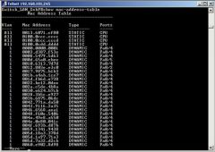
CLI command that lists all known MAC addresses in the MAC table |
|
|
Show mac address-table dynamic |
shows all the dynamically learned MAC addresses |
|
|
show interfaces status |
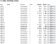
CLI commands, shows the status of the interfaces. |
|
|
show interfaces f0/1 counters |
CLI command lists statistics about incoming and outgoing frames on the interfaces |
|
|
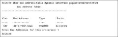
show mac address-table dynamic interface |
|
|
|
show mac address-table aging-time |
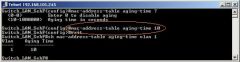
Switches remove entries that have not been used for a defined number of seconds, 300 seconds is default in most switches |
|
|
clear mac address-table dynamic |
Empties the MAC table of all dynamic entries |
|
|
CLI steps to configure console password |
line console 0 login password hope |
|
|
CLI steps to configure telnet password |
line vty 0 15 login password love |
|
|
CLI steps to configure secret password |
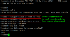
enable secret password |
|
|
CLI steps to configure local username and password |
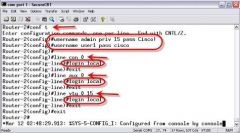
line console 0 login local username wendell secret odom line vty 0 15 login local username chris secret brown |
|
|
AAA |
Authorization, Accounting, Authentication. |
|
|
AAA Server |
A server that holds security information and provides services related to user login, usually used for login into cisco switches |
|
|
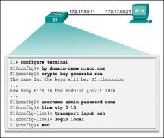
CLI steps to configure SSH on a switch |
|
|
|
Transport input all Transport input telnet ssh Transport input none Transport input telnet Transport input ssh |
Supports telnet and ssh Supports telnet and ssh Supports neither Supports only telnet Supports only ssh |
|
|
Show ip ssh |
Verifies that the SSH server is enabled and view the version and configuration data |
|
|
Show ssh |
Lists information about the clients currently connected via ssh |
|
|
CLI steps for configuring IPv4 address on cisco switch |
SW1#config t SW1 (config)#interface vlan 1 SW1 (config-if)ip address 192.168.1.200 255.255.255.0 SW1 (config-if)no shudown SW1 (config-if)exit SW1 (config)ip default-gateway 192.168.1.1 |
|
|
CLI steps for a switch to learn its IP address via DHCP |
SW1#config t SW1 (config)#interface vlan 1 SW1 (config-if)#ip address dhcp SW1 (config-if)#no shutdown |
|
|
show running-config |
list the currently used configuration |
|
|
show dhcp lease |
Lists any information the switch acquires as a DHCP client. This includes IP address, subnet mask, and default gateway information |
|
|
show crypto key mypubkey rsa |
Lists the public and shared key created for use with SSH usin the crypto key generate rsa global configuration command |
|
|
terminal history size x |
Changes the length of the history buffer for the current user only, only for the current login to the switch |
|
|
show history |
Lists the commands in the current history buffer |
|
|
logging synchronous |
Console or vty mode. Tells IOS to send log messages to the user at natural break points between commands rather than in the middle of a line of output |
|
|
[no] logging console |
Global commands that disables or enables the display of log messages to the console |
|
|
exec-timeout minutes [seconds] |
Console or vty mode. Sets the inactivity timeout, so that after the defined period of no action, IOS closes the current user login session. |
|
|
speed {10|100|1000|auto} |
interface mode. Manually sets the speed to the listed speed or, with the auto setting, automatically negotiates the speed. |
|
|
duplex {auto|full|half} |
Interface mode. Manually sets the duplex to half or full, or to autonegotiate the duplex setting |
|
|
description text |
Interface mode. Lists any information text that the engineer wants to track for the interface, such as the expected device on the other end of the cable |
|
|
no duplex no speed no description |
Reverts to the default settings for each interface subcommand of speed auto, duplex auto, and the absence of a description command. |
|
|
Whats a switch speed and duplex default setting from the box |
autonegotiation |
|
|
IEEE autonegotiation |
user the slowest supported speed (often 10Mbps) and if speed is 10 or 100 use half duplex, otherwise use full duplex |
|
|
Cisco autonegotiation |
sense the speed without autonegotiation, but if it fails, default to IEEE standards. If speed is 10 or 100 use half duplex, otherwise use full duplex |
|
|
Hubs and autonegotiation |
They use the IEEE rules for choosing default settings and it also uses CSMA/CD algorithing to avoid collisions |
|
|
Port security |
A Cisco switch feature in which the switch watches Ethernet frames that come in an interface (a port) tracks the source MAC addresses of all such frames, and takes a security action if the number of different such MAC addresses is exceeded. |
|
|
Configuring port security |
1. Make the switch interface either a static access or trunk interface using the switchport mode access or the switchport mode trunk interface subcommands, respectively 2. Enable port security using the switchport port-security interface subcommand. 3. (Optional) Override the default maximum number of allowed MAC addresses associated with the interface (1) by using the switchport port-security maximum number interface subcommand. 4. (Optional) Override the default action to take upon a security violation (shutdown) using the switchport port-security violation {protect|restrict|shutdown} interface subcommand. 5. (Optional) Predefine any allowed source MAC addresses for this interface using the switchport port-security mac-address mac-address command. Use the command multiple times to define more than one MAC address. 6. (Optional) Tell the switch to "sticky learn" dynamically learned MAC addresses with the switchport port-security mac-address sticky interface subcommand |
|
|
Switchport port-security violation protect |
Discards offending traffic. |
|
|
Switchport port-security violation restrict |
Discards offending traffic, sends log and SNMP messages, Increments the violation counter for each violating incoming frame. |
|
|
Switchport port-security violation shutdown |
Discards offending traffic, sends log and SNMP messages, Increments the violation counter for each violating incoming frame, and disables the interface by putting it in an err-disabled state, discarding all traffic. |
|
|
show mac address-table secure [interface type number] |
Lists MAC addresses defined or learned on ports configured with port security |
|
|
show port-security interface type number |
Lists an interface's port security configuration settings and security operational status |
|
|
show port-security |
Lists one line per interface that summarizes the port security settings for any interface on which it is enabled. |
|
|
CSMA/CD |
Carrier sense multiple access with collision detection. A media access mechanism in which devices ready to transmit data first check the channel for a carrier. If no carrier is sensed for a specific period of time, a device can transmit. If two devices transmit at once, a collision occurs and is detected by all colliding devices. This collision subsequently delays retransmissions from those devices for some random length of time. |
|
|
What kind of topology to hubs have |
Star topology |
|
|
What are transparent bridges or bridges |
They sit in between hubs and divide network into multiple collision domains |
|
|
Key things about collision domains |
1. LAN switches and bridges place each separate interface into a separate collision domain 2. Routers place each LAN interface into a separate collision domain 3. LAN hubs do not place each interface into a separate collision domain 4. A modern LAN, with all LAN switches and routers, with full duplex on each link would not have collisions at all. But you should look at each Ethernet link as a separate collision domain in case of troubleshooting |
|
|
Key points about broadcast domains |
1. VLANs are broadcast domains 2. Routers, because they do not forward LAN broadcasts, create separate broadcast domains off their separate Ethernet interfaces. |
|
|
Campus LAN |
LAN created to support devices in a building or in multiple building in somewhat close proximity to one another |
|
|
Two-tier campus design |
Provides a place to connect end-user devices, and connects all access switches to the distribution switches. Also known as "collapsed core" |
|
|
Access switches |
Connect directly to end users, providing user device access to the LAN |
|
|
Distribution switches |
Provide a path through which the access switches can forward traffic to each other |
|
|
Star topology |
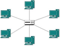
Design where one device connects to several others |
|
|
Full mesh topology |
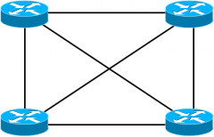
All the links connect to each other |
|
|
Partial mesh topology |
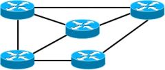
Some links connect to others and some do not |
|
|
Hybrid topology |
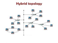
A design that combines topology design concepts into a larger more complex design |
|
|
Three-Tier design |
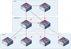
Access layer provides connection for end-user devices, distribution layer provides an aggregation point for access switches, providing connectivity to the rest of the devices on the LAN, forwarding frames between switches, but not connecting directly to end-user devices. Core layer aggregates distribution switches in very large campus LANs, providing very high forwarding rates for the larger volume traffic |
|
|
802.3i |
10BASE-T, Ethernet, 10 Mbps, UTP, 100m |
|
|
802.3u |
100BASE-T, Fast Ethernet, 100 Mbps, UTP, 100m |
|
|
802.3z |
1000BASE-X, Gigabit Ethernet, 1000 Mbps (1 Gbps), Fiber |
|
|
802.3ab |
1000BASE-T, Gigabit Ethernet, 1000 Mbps, UTP, 100m |
|
|
802.3ae |
10GBASE-X, 10 GigE, 10 Gbps, Fiber |
|
|
802.3an |
10GBASE-T, 10 GigE, 10 Gbps, UTP |
|
|
802.3ba |
40GBASE-X, 40 GigE, 40 Gbps, Fiber |
|
|
802.3ba |
100GBASE-X, 100 GigE, 100 Gbps, Fiber |
|
|
1000BASE-SX |
Multimode fiber, 550m |
|
|
1000BASE-LX |
Multimode fiber or singlemode fiber, 550m |
|
|
WLAN |
Wireless LAN controller, it controls and manages all AP functions |
|
|
LWAP |
Lightweight AP, forwards data between the wired and wireless LAN, and specifically forwarding data through the WLC using a protocol like CAPWAP |
|
|
Benefits of VLAN's |
1. Reduce CPU overhead on each device by reducing the number of devices that receive each broadcast frame 2. Reduce security risk by reducing the number of hosts that receive copies of frames that the switches flood 3. To improve security for hosts that send sensitive data by keeping those hosts on a separate VLAN 4.Create more flexible designs that group users by department, or by groups that work together 5. To solve problems more quickly, because the failure domain for many problems is the same set of devices as those in the same broadcast domain 6. To reduce the workload for the STP by limiting a VLAN to a single access switch. |
|
|
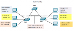
VLAN trunking |
A Cisco proprietary messaging protocol used between cisco switches to communicate configuration information about the existence of VLAs, including the VLAN ID and VLAN name |
|
|
VLAN tagging and VLAN ID |
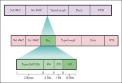
The sending switch adds another header to the frame before sending it over the trunk. This extra trunking header includes a VLAN ID field so that the sending switch can associate the frame with a particular VLAN ID, and the receiving switch can then know in what VLAN each frame belongs. |
|
|
ISL |
Inter-Switch Link is a cisco-proprietary protocol that maintains VLAN information as traffic flows between switches and routers. |
|
|
802.1Q |
The IEEE standardized protocol for VLAN trunking. It also uses the native VLAN which is usually VLAN 1, whenever a frame is sent and receive that does not have the 802.1Q header, it is assumed that the frame is for the native VLAN. Both switches must have the same native VLAN. |
|
|
Key things about VLAN's |
1. In a LAN, the devices in the VLAN need to be in the same subnet unless some devices are supposed to be in a different VLAN, then in that case they need to be in a different subnet. 2. Layer 2 switches can't route between VLAN's but layer 3 switches can. 3. Routers can route between VLAN's either by being connected with one cable to each switch or by using the method "router-on-a-stick" which makes one connection to the router a trunk connection |
|
|
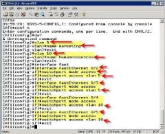
Configuring steps for setting up VLAN trunking on a cisco switch via the CLI |
|
|
|
show vlan brief |
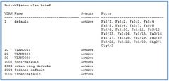
Shows vlan, status, and configured to what vlan, it also shows names of vlan's, does not include operational trunks |
|
|
Switchport mode access |
Interface mode. Always act as an access (nontrunk) port |
|
|
Switchport mode trunk |
Interface mode. Always act as a trunk port |
|
|
Switchport mode dynamic desirable |
Interface mode. Initiates negotiation messages and responds to negotiation messages to dynamically choose whether to start using trunking |
|
|
Switchport mode dynamic auto |
Interface mode. Passively waits to receive trunk negotiation messages, at which point the switch will respond and negotiate whether to use trunking |
|
|
Data VLAN |
Same idea and configuration as the access VLAN on an access port, but defined as the VLAN on that link for forwarding the traffic for the device connected to the phone on the desk. |
|
|
Voice VLAN |
The VLAN defined on the link for forwarding the phone's traffic. Traffic in this VLAN is typically tagged with an 802.1Q header.
|
|
|
Key things about IP telephony ports on switches |
1. Configure these ports like a normal access port to begin: Configure it as a static access port and assign it an access VLAN 2. Add one more command to define the voice VLAN switchport voice vlan 1 3. Look for the mention of the voice VLAN ID, but no other new facts, in the output of the show interfaces type number switchport command 4. Look for both the voice and data (access) VLAN IDs in the output of the show interfaces type number trunk command. 5. Do not expect to see the port listed in the list of operational trunks as listed by the show interfaces trunk command. |
|
|
vtp mode {server|client|transparent|off} |
Gloval config command that defines the VTP mode |
|
|
switchport access vlan vlan-id |
Interface subcommand that statically configures the interface into that one VLAN |
|
|
switchport trunk encapsulation {dot1q|isl|negotiate} |
Interface subcommand that defines which type of trunking to use, assuming that trunking is configured or negotiated |
|
|
switchport nonegotiate |
Interface subcommand that disables the negotiation of VLAN trunking |
|
|
show vtp status |
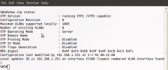
Lists VTP configuration and status information. |
|
|
Troubleshooting steps
|
2. Resolve or escalate 3. Verify or monitor |
|
|
What to look for when troubleshooting
|
2. Analyze where switches will forward frames (checking the MAC address and destination) 3. Analyze port security 4. Analyze VLANs and VLAN trunking |
|
|
what does up|down|notconnect mean in a switch interface status
|
Not expected on LAN switch physical interfaces |
|
|
what does a down|down|err-disabled mean in a switch interface status
|
Por security has disabled the interface |
|
|
Runts
|
Frames that did not meet the minimum frame size requirement, can be caused by collisions |
|
|
Giants
|
Frames that exceed the maximum frame size requirement |
|
|
Input Errors
|
A total of many counters, including runts, giants, no buffer, CRC, frame, overrun, and ignored counts. |
|
|
CRC |
Received frames that did not pass the FCS math; can be caused by collisions. |
|
|
Frame
|
Received frames that have an illegal format, for example, ending with a partial byte; can be caused by collisions. |
|
|
Packets Output |
Total number of packets (frames) forwarded out the interface |
|
|
Output Errors |
Total number of packets (frames) that the switch port tried to transmit, but for which some problem occurred. f |
|
|
Collisions
|
Counter of all collisions that occur when the interface is transmitting a frame |
|
|
Late Collisions |
The subset of all collisions that happen after the 64th byte of the frame has been transmitted |
|
|
Steps to analyze the forwarding path
|
2. Make a forwarding decision, look at the frames destination MAC in the MAC address table, but only for the entires in the VLAN identified in step 1. If the destination MAC is... found (unicast) forward the frame out the only interface listed in the matched address table entry. Not found (unicast), flood the frame out all other access ports except incoming port in the same VLAN. Broadcast, flood the frame, with the same rules as the previous step. |
|
|
Three basic features that port security uses to determine which frames to filter.
|
2. Limit the number of MAC addresses using the interface, discarding frames to/from MAC addresses learned after the maximum limit is reached. 3. A combination of the previous two points. |
|
|
Steps to analyze port security operation on an interface
|
1. Identify all interfaces on which port security is enabled (show running-config or show port-security.) 2. Determine whether a security violation is currently occurring based in part on the violation mode of the interface's port security configuration. shutdown/restrict/protect 3. Compare the port security configuration to the diagram and to the Last Source Address field in the ouput of the show port-security interface command. |
|
|
Router (config-if)# switchport port-security violation shutdown
|
The interface will be in an err-disabled state, and the port security port status will be secure-down |
|
|
Router (config-if)# switchport port-security violation restrict
|
The interface will be in a connected state, the port security port status will be secure-up, but the show port-security interface command will show an incrementing violations counter
|
|
|
Router (config-if)# switchport port-security violation protect
|
The interface will be in a connected state, and the show port-security interface command will not show an incrementing violations counter
|
|
|
Steps to analyze VLANs and VLAN trunks
|
2. Determine whether the VLANSs both exist (configured or learned with VTP) and are active on each switch. 3. Check the allowed VLAN lists, on the switches on both ends of the trunk, and ensure that the lists of allowed VLANs are the same 4. Check for incorrect configuration settings that result in one switch operating as a trunk, with the neighboring switch not operating as a trunk. |
|
|
True or False Switches configured as VTP servers and clients do not list the VLAN commands in the running-config nor the startup-config file. |
True |
|
|
Key facts about subnets |
1. Addresses in the same subnet are not separated by a router 2. Addresses in a different subnet are separated by at least one router |
|
|
How to determine the number of subnets |
You should plan for one subnet for every VLAN, point-to-point serial link, and ethernet emulation WAN link (EoMPLS) |
|
|
Whats the formula to determine subnet size |
2 to the h power - 2 (one for subnet and one for subnet broadcast) |
|
|
Features that extended the life of IPv4 |
1. IPv6, larger address, 128 bit 2. Assigning a subset of public IP network to each company, instead of an entire public IP network, to reduce waste 3. NAT, which allows the use of private IP network |
|
|
Class A private |
10.0.0.0 |
|
|
Class B private |
172.16.0.0 through 172.31.0.0 |
|
|
Class C private |
192.168.0.0 through 192.168.255.0 |
|
|
An unsubnetted classful network is made up of how many parts |
2, network part and host part |
|
|
A subnetted classful network is made up of how many parts |
3, network, subnet, host |
|
|
What are the three parts of a subnet |
Subnet number, subnet broadcast, and IP address |
|
|
Subnet number |
Also called the subnet ID or subnet address, this number identifies the subnet. It is the numberically smallest number in the subnet. It can't be used as an IP address by a host. |
|
|
Subnet broadcast |
Also called the subnet broadcast address or directed broadcast address, this is the last (numerically highest) number in the subnet. It also can't be used as an IP address by a host. |
|
|
IP addresses |
All the numbers between the subnet ID and the subnet broadcast address can be used as a host IP address. |
|
|
VLSM |
Variable- length subnet masks, the capability to specify a different subnet mask for the same Class A, B, or C network number on different subnets. |
|
|
Binary mask |
An IPv4 subnet mask written as a 32-bit binary number |
|
|
DDN |
Dotted-decimal notation, The format used for IPv4, in which four decimal values are used, separated by periods (dots) |
|
|
Decimal mask |
An IPv4 subnet mask written in dotted decimal notations: Ex 255.255.255.0 |
|
|
Prefix mask |
A term to describe an IPv4 subnet mask when represented as a slash (/) follwed by a decimal number. |
|
|
CIDR Masks |
Another term for a prefix mask, one that uses prefix or CIDR notation, in which the mask is represented by a slash (/) followed by a decimal number |
|
|
How to determine prefix, network, subnet, and hosts |
1. Convert the mask to prefix format. 2. Determine network based on the class 3. Calculate subnet = prefix - network 4. Calculate hosts = 32 - prefix 5. Calculate hosts/subnet = 2 to the power of h - 2 6. Calculate number of subnet = 2 to the power of subnets |
|
|
Steps to install a router |
1. Connect any LAN cables to the LAN port. 2. If using an external CSU/DSU, connect the router's serial interface to the CSU/DSU and the CSU/DSU to the line from the telco 3. If using internal CSU/DSU, connect the router's serial interface to the line from telco 4. Connect the router's console port to a PC (using a rollover cable), as needed, to configure the router. 5. Connect a power cable from a power outlet to the power port on the router 6. Power on the router |
|
|
Differences in router CLI compared to switch CLI |
1. Switches use VLAN interfaces, routers use an IP address configured on each working interface 2. Routers have an aux port meant for an external modem and phone line for remote users to log into the router 3. Router IOS by default disallow both Telnet and SSH because of default setting transport input none in vty configuration mode. |
|
|
Interface line status |
Refers to the Layer 1 status |
|
|
Protocol status |
Refers generally to the Layer 2 status |
|
|
CLI command clock rate 60 |
Interface command that sets the seed at which the router supplies a clocking signal, applicable only when the router has a DCE cable installed. The unit is bits/second. |
|
|
show ip interface brief |
Lists a single line of information about each interface, IP address, line and protocol status, and the method with which the address was configured (manual or DHCP) |
|
|
show protocols [type number] |
Lists information about the listed interface (or all interfaces if the interface is omitted), including the IP address, mask and line/protocol status. |
|
|
Show controllers [type number] |
Lists many lines of information per interface, or for one interface, for the hardware controller of the interface. On serial interfaces, this command identifies the cable as either a DCE or DTE cable |
|
|
Steps taken by a host when forwarding IP packets |
1. If destination is local send directly. Find destination hosts MAC address. Use the already-known ARP table entry, or use ARP messages to learn information. Encapsulate the IP packet in a data-link frame, with the destination data-link address of the destination host. 2. If the destination is not local, send to the default gateway: Find the defaults gateway MAC address. Use the already-known ARP table entry, or use ARP messages to learn the information. Encapsulate the IP packet in a data-link frame, with the destination data-link address of the default gateway. |
|
|
Steps taken by a router when forwarding IP packets |
1. For each received data-link frame, choose whether or not to process the frame. Process it if (A) The frame has no errors per FCS field (B) The frame's destination data-link address is the router's address (or an appropriate multicast or broadcast address) 2. If choosing to process the frame at Step 1, de-encapsulate the packet from inside the data-link frame by removing header and trailer 3. Compare the packet's destination IP address to the routing table and find the route that matches the destination address. This route identifies the outgoing interface of the router and possibly the next-hop router. 4. Encapsulate the packet into a data-link frame appropriate for the outgoing interface by attaching a HDLC header (next routers MAC) and trailer. When forwarding out LAN interfaces, use ARP as needed to find the next device's MAC address 5. Transmit the frame out the outgoing interface, as listed in the matched IP route. |
|
|
Three common sources from which routers build IP routes |
1. Connected routes: Added because of the configuration of the ip address interface subcommand on the local router 2. Static routes: Added because of the configuration of the ip route gloval command on the local router 3. Routing protocols: Added as a function by configuration on all routers, resulting in a process by which routers dynamically tell each other about the network so thatt they all learn routes. |
|
|
Rules regarding when a router creates a connected router |
1. The interface is in a working state. 2. The interface has an IP address assigned through the ip address interface subcommand |
|
|
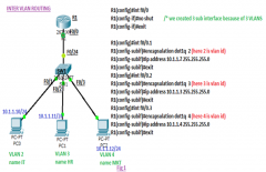
Three options for connecting a router to each VLAN |
1. Use a router, with one router LAN interface and cable connected to the switch for each and every VLAN. 2. Use a router, with a VLAN trunk connecting to a LAN switch. 3. Use a Layer 3 switch |
|
|
Concept of VLAN subinterfaces on a router |
1. Use the interface type number.subint command in gloval configuration mode to create a unique subinterface for each VLAN that needs to be routed. 2. Use the encapsulation dot1q vlan_id command in subinterface configuration mode to enable 802.1Q and associate one specific VLAN with the subinterface. 3. Use the ip address address mask command in the subinterface configuration mode to configure IP settings (address and mask) |
|
|
Two alternative methods to configure the native VLAN in a ROAS configuration |
1. Configure the ip address command on the physical interface, but without an encapsulation command; the router considers this physical interface to be using the native VLAN 2. Configure the ip address command on a subinterface, and use the encapsulation...native subcommand. |
|
|
Layer 3 Switching concept and configuration |
1. On 2960 switches use the sdm prefer lanbase-routing in global config mode and reload the switch 2. Use the ip routing command in gloval configuration mode to enable IPv4 routing on the switch 3. Use the interface vlan vlan_id command in global configuration mode to create VLAN interfaces for each VLAN for which the layer 3 switch is routing packets 4. Use the ip address address mask command in interface config mode to config an IP address and mask on the VLAN interface, enabling IPv4 on that VLAN interface. 5. Use the no shutdown command in interface configuration mode to enable the VLAN interface |
|
|
Troubleshooting checklist for routes that do appear in the IP routing table |
1. Is there a subnetting math error in the subnet ID and mask? 2. Is the next-hop IP address correct, and referencing an IP address on a neighboring router? 3. Is the outgoing interface correct. and referencing an interface on the local route |
|
|
Troubleshooting checklist for static routes that do not appear in the IP routing table |
1.The outgoing interface listed in the Troubleshooting checklist for routes that do appear in the IP routing table ip route command is not up/up 2. The next-hop router IP address listed in the ip route command is not reachable 3. A better competing router exists, and that competing route has a better (lower) administrative distance. |
|
|
encapsulation dot1q vlan-id [native] |
A subinterface subcommand that tells the router to use 802.1Q trunking, for a particular VLAN, and with the native keyword, to not encapsulate in a trunking header |
|
|
encapsulation isl vlan-identifier |
A subinterface subcommand that tells the router to use ISL trunking for a particular VLAN |
|
|
sdm prefer lanbase-routing |
A command on Cisco switches that enables the switch to support IP routing if configured |
|
|
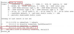
show ip router |
Lists the router's entire routing table |
|
|
show ip route [connected | static | rip] |
Lists a subset of the IP routing table |
|
|
show ip route ip address |
Lists detailed information about the route that a router matches for the listed IP address
|
|
|
show vlans |
Lists VLAN configuration and statistics for VLAN trunks configured on router |
|
|
show arp, show ip arp |
Lists the router's IPv4 ARP table |
|
|
clear ip arp [ip-address] |
Remves all dynamically learned ARP table entires |
|
|
default gateway/router |
On an IP host, the IP address of some router to which the host sends packets when the packet's destination address is on a subnet other than the local subnet
|
|
|
ARP table |
A list of IP addresses of neighbors on the same VLAN, along with their MAC addresses, as kept in memory by hosts and routers
|
|
|
next-hop router |
In an IP route in a routing table, part of a routing table entry that refers to the next IP router that should receive packets that patch the route.
|
|
|
outgoing interface |
In an IP route in a roruting table, part of a routing table entry that refers to the local interface out which the local router should forward packets that match the route. |
|
|
sub interface |
One of the virtual interfaces on a single physical interface.
|
|
|
VLAN interface |
A configuration concept inside Cisco switches, used as an interface between IOS running on the switch and a VLAN supported inside the switch, so that the switch can assign an IP address and send IP packets into that VLAN.
|
|
|
Connected route |
On a router, an IP route added to the routing table when the router interface is both up and has an IP address configured. The route is for the subnet that can be calculated based on the configured IP address and mask.
|
|
|
static route |
An IP route on a router created by the user configuring the details of the route on the local router.
|
|
|
default route |
On a router, the route that is considered to match all packets that are not otherwise matched by some more specific route.
|
|
|
host route |
A route with a /32 mask, which by irtue of this mask represents a route to a single host IP address.
|
|
|
floating static route |
A static IP route that uses a higher administrative distance that other routes, typically routes learned by a routing protocol. As a result, the router will not use the static route if the routing protocol route has been learned, but then use the static route if the routing protocol fails to learn the route.
|
|
|
network route |
A route for a classful network.
|
|
|
administrative distance |
A means for one router to choose between multiple routes to reach the same subnet when those routes were learned by different routing protocols. The lower the AD, the better the source of the routing information. |
|
|
Comparisons of IGP's |
1. Is it distance vector or link state 2. Choosing the best route based on the metric 3. The speed of convergence 4. Is the protocol public standard (RIP, OSPF) or vendor standard (EIGRP) |
|
|
distance vector |
The logic behind the behavior of some interior routing protocols, such as RIP. DV routing algorithms call for each router to send its entire routing table in each update, but only to its neighbors. DV algorithms can be prone to routing loops but are simpler than link-state routing algorithms. |
|
|
Split horizon |
A distance vector feature that tells a router to omit some routes from an update sent out an interface |
|
|
route poisoning |
The practice of advertising a failed route, but with a special metric value called infinity. |
|
|
Key features of RIPv1 |
1. Hop-count metric 2. Sets 15 as the largest metric for a working route 3. Sends full routing updates 4. Uses split horizon 5. Uses route poisoning, with metric 16 to mean "infinite" |
|
|
Key features of RIPv2 |
1. Hop-count metric 2. Sets 15 as the largest metric for a working route 3. Sends full routing updates 4. Uses split horizon 5. Uses route poisoning, with metric 16 to mean "infinite" But it also does a few more things unlike RIPv1 1.Sends mask in routing update, thereby supporting VLSM 2. Supports manual route summarization 3. Sends update to 224.0.0.9 multicast address' 4. Supports authentication |
|
|
Whats does RIPv2 do on a interface once enabled? |
1. The router sends routing updates out the interface 2. The router listens for an processes incoming updates on that same interface 3. The router advertises about the subnet connected to the interface |
|
|
show ip route |
|
|
|
Administrative distance for connected routes |
0 |
|
|
Administrative distance for static routes |
1 |
|
|
Administrative distance for EIGRP |
90 |
|
|
Administrative distance for OSPF |
110 |
|
|
Administrative distance for RIPv1 and v2 |
120 |
|
|
Administrative distance for DHCP default route |
254 |
|
|
Administrative distance for unknown |
255 |
|
|
Contiguous network |
A network topology in which the subnets of network X are not separated by subnets of any other classful network |
|
|
Discontiguous network |
A network topology in which the subnets of network X are separated by subnets of some other classful network |
|
|
RIP troubleshooting issues |
1. The RIP network command controls where RIP operates. If a missing network command fails to enable RIP on an interface: (A) RIP will not advertise about that connected subnet and (B) RIP will not send advertisements out that interface or process received advertisements in that interface 2. The passive-interface command should not be used for interfaces that connect to other routers. 3. The no auto-summary command has an impact only on routers that directly connect to more than one classful network. However, the command is needed only if a discontiguous classful network exists. 4. Some non-RIP features impact RIP operation, namely... (A) Interfaces must bbe working for RIPv2 to use the interfaces (B) Two routers on the same link must have IP addresses in the same subnet for RIPv2 to exchange routing information (C) Note that ACLs can filter RIP update messages and therefore break RIP |
|
|
EGP |
Exterior gateway protocol, A routing protocol that was designed to exchange routing information between different autonomous systems |
|
|
metric |
A unit of measure used by routing protocol algorithms to determine the best route for traffic to use to reach a particular destination |
|
|
routing update |
A generic reference to any routing protocols messages in which it sends routing information to a neighbor |
|
|
passive interface |
With a routing protocol, a router interface for which the routing protocol is enabled on the interface, but for which the routing protocol does not send routing protocol messages out that interface |
|
|
autosummarization |
A routing protocol feature in which in which the router that sits at the boundary between different classful networks will automatically advertise a route for one entire classful network into the other classful network, and vice versa |
|
|
hop count |
The metric used by the RIP routing protocol. Each router in an IP route is considered a hop, so for example, if two other routers sit between a router and some subnet, that router would have a hop count of two for that route. |
|
|
CLI command router rip |
Global command that moves the user into RIP configuration mode |
|
|
CLI command network network-number |
RIP subcommand that lists a classful network number, enabling RIP on all of that router's interfaces in that classful network |
|
|
CLI command passive-interface default |
RIP subcommand that changes the default setting on RIP-enable interfaces to be passive instead of not passive |
|
|
CLI command no passive-interface {interface-type interface-number} |
RIP subcommand that tells RIP to no longer advertise RIP updates on the listed interface |
|
|
CLI command [no] auto-summary |
RIP subcommand that toggles on (auto-summary) and off (no auto-summary) the autosummarization feature of RIP |
|
|
CLI command maximum-paths number |
RIP subcommand that sets the number of equal-metric routes for the same subnet that RIP will add to the IP routing table |
|
|
CLI command default-information originate |
RIP subcommand that causes RIP to adverise a default route- a route for prefix 0.0.0.0 mask 0.0.0.0 - if the local router has a default route in its routing table already |
|
|
CLI command ip address dhcp |
Interface subcommand that causes a router to act as a DHCP client, learning the IPv4 address to use on the interface and dynamically learning a default route that uses the DHCP-announce default gateway address as the next-hop IP address in a static route. |
|
|
Whats the process to lease an IP address between a client and a server |
DORA Discover: Sent by the DHCP client to find a willing DHCP server Offer: Sent by a DHCP server to offer to lease to that client a specific IP address Request: Sent by the DHCP client to ask the server to lease the IPv4 address listed in the Offer message Acknowledgment: Sent by the DHCP server to assign the address, and to list the mask, default router, and DNS server IP address |
|
|
IP addresses that allow a DHCP host with no IP address to still be able to send and receive messages on the local subnet |
0.0.0.0 An address reserved for use as a source IPv4 address for hosts that do not yet have an IP address 255.255.255.255 The local broadcast IP address. Packets sent to this destination address are broadcast on the local data link, but routers do not forward them. |
|
|
Four logic steps created by the ip helper-address command |
1. Watch for incoming DHCP messages, with destination IP address 255.255.255.255 2. Change that packet's source IP address to the router's incoming interface IP address from the host. 3. Change that packet's destination IP address to the address of the DHCP server (as configured in the ip helper-address command) 4. Route the packet to the DHCP server |
|
|
DHCP troubleshooting checklist |
1. If using a centralized DHCP server, at least one router on each remote subnet that has DHCP clients must act as DHCP relay agent, and have a correctly configured ip helper-address address subcommand on the interface connected to that subnet. 2. If using a centralized IOS DHCP server, make sure the DHCP pools network commands match the entire network's list of router interfaces that have an ip helper-address command pointing to this DHCP server. 3. Troubleshoot for any IP connectivity issues between the DHCP relay agent and the DHCP server, using the relay agent interface IP address and the server IP address as the source and destination of the packets. 4. Troubleshoot for any LAN issues between the DHCP client and the DHCP relay agent. |
|
|
Verification checklist for comparing host IPv4 settings with default router IPv4 settings |
1. The host link to the LAN and the default router link to the LAN must be in the same VLAN 2. The host and default router IP addresses must be in the same subnet 3. The host default router setting must refer to the same IP address configured on the router. (In other words, if the host claims the default router is 10.1.1.1, make sure the router interface IP address is not 10.1.1.2) 4. The LAN switches must not discard the frame because of the port security configuration. |
|
|
Different types of IPv4 broadcast addresses |
1. Local broadcast address: 255.255.255.255. Used to send a packet on a local subnet, knowing that routers will not forward the packet as in. Also called a limited broadcast. 2. Subnet broadcast address: One reserved address for each subnet. A packet sent to a subnet broadcast address can be routed to the router connected to that subnett, and then sent as a data link broadcast to all hosts in that one subnet. Also called an all-hosts broadcast or directed broadcast. 3. Network broadcast address: One reserved address for each classful network, namely the numerically highest number in the network. Used to send one packet to all hosts in that one network. Also called an all-subnets broadcast, referring to the fact that the packet reaches all subnets in a network. |
|
|
Unicast address are used for... |
web, email, chat, assigned to hosts with DHCP, and uses A/B/C classes |
|
|
Broadcast address are used for... |
Primarily used by protocols like DHCP and ARP to send to multiple devices, and used as destination IP address only |
|
|
Multicast address are used for... |
Used as destination IP address only, used by applications to send the same data at the same time to multiple clients, and is class D address. |
|
|
CLI command ip dhcp exluded-address first last |
A gloval command that reserves an inclusive range of addresses, so that the DHCP server function does not lease out these addresses. |
|
|
CLI command ip dhcp pool pool-name |
A global command that creates a pool, by name, and moves the user to DHCP server pool configuration. |
|
|
CLI command network subnet-id {ddn-mask |/prefix-length} |
A DHCP pool mode subcommand that defunes a network or subnet causing the DHCP server to lease out IP addresses in that subnet |
|
|
CLI command default-router address1 address2... |
A DHCP pool mode subcommand that defines one or more routers as default routers, with that information passed for clients served by this pool |
|
|
CLI command dns-server address1 address2 |
A DHCP pool mode subcommand that defines the list of DNS servers that the DHCP server will list for clients served by this pool |
|
|
CLI command lease {days[hours[minutes]] infinite} |
A DHCP pool mode subcommand that defines the length of time for a DHCP lease, for clients served by this pool |
|
|
CLI command ip helper-address IP-address |
An interface subcommand that tells the router to notice local subnet broadcasts (to 255.255.255.255) that use UDP, and change the source and destination IP address, enabling DHCP server to sit on a remote subnet. |
|
|
CLI command show arm, show ip arp |
Lists the router's IPv4 ARP table |
|
|
CLI command show ip dhcp binding |
Lists the currently leased IP addresses on a DHCP server, along with the client identifier and lease time information |
|
|
CLI command show ip dhcp pool name |
Lists the configured range of addresses in the pool, along with usage statistics and utilization high/low-water marks |
|
|
CLI command show ip dhcp server statistics |
Lists statistics about the request by the DHCP server |
|
|
CLI command show ip dhcp conflict |
Lists the IP addresses that the DHCP server found were already in use when the server tried to lease the address to a host |
|
|
CLI command clear ip dhcp conflict |
Removes all entries from the DHCP servers conflict list |
|
|
Calculate the shortest prefix mask based on the minimum value of subnets |
P = N + S |
|
|
Calculate the shortest prefix mask based on the minimum value of hosts |
P = 32 - H |
|
|
The shorter three-step process to find all prefix masks that meet certain requirements |
The process to find the masks just requires a few steps, after you know N and the minimum values of S and H. The process finds the value of /P when using the least number of subnet bits, and when using the least number of host bits, as follows: Step 1.Calculate the shortest prefix mask (/P) based on the minimum value of S, where P = N + S. Step 2.Calculate the longest prefix mask (/P) based on the minimum value of H, where P = 32 – H. Step 3.The range of valid masks includes all /P values between the two values calcu-lated in the previous steps. |
|
|
Reasons to choose one subnet mask versus another |
To maximize the number of hosts/subnet: To make this choice, use the shortest prefix mask (that is, the mask with the smallest /P value), because this mask has the largest host part. To maximize the number of subnets: To make this choice, use the longest prefix mask (that is, the mask with the largest /P value), because this mask has the largest subnet part. To increase both the numbers of supported subnets and hosts: To make this choice, choose a mask in the middle of the range, which gives you both more subnet bits and more host bits. |
|
|
Classless routing protocols |
RIPv2, EIGRP, OSPF. They all support VLSM |
|
|
Classfull routing protocols |
RIPv1 |
|
|
Steps when adding a new subnet to existing VLSM design |
Step 1. Pick the subnet mask (prefix length) for the new subnet, based on the designrequirements (if not already listed as part of the question). Step 2. Calculate all possible subnet numbers of the classful network using the maskfrom Step 1, along with the subnet broadcast addresses. Step 3. Make a list of existing subnet IDs and matching subnet broadcast addresses. Step 4. Compare the existing subnets to the candidate new subnets to rule out overlappingnew subnets. Step 5. Choose the new subnet ID from the remaining subnets identified at Step 4,paying attention to whether the question asks for the numerically lowest ornumerically highest subnet ID. |
|
|
Classful routing protocol |
Does not transmit the mask information along with the subnet number, and therefore must consider Class A, B, and C network boundaries and perform autosummarization at the those boundaries. Does not support VLSM. |
|
|
Classless routing protocol |
An inherent characteristic of a routing protocol, specifically that the routing protocol does send subnet masks in its routing updates, thereby removing any need to make assumption about the addresses in a particular subnet or network, making it able to support VLSM and manual route summarization. |
|
|
Overlapping subnets |
An incorrect IP subnet design condition in which one subnet's range of addresses includes addresses in the range of another subnet. |
|
|
VLSM |
The capability to specify a different subnet mask for the same Class A, B, or C network number on different subnets. VLSM can help optimize available address space. |
|
|
Types of root causes of host connectivity problems that cannot be found by router ping commang |
■ ACLs that discard packets based on host A’s IP address, while that same ACL permitspackets matched on the router’s IP address ■ LAN switch port security issues that filter A’s packets (based on A’s MAC address) ■ IP routes on routers that happen to match host A’s 172.16.1.51 address, with differentroutes that match R1’s 172.16.1.1 address ■ Problems with host A’s default router setting |
|
|
Network layer problems that could cause a ping to fail between a route and host on the same LAN subnet |
■ IP addressing problem: Host A could be statically configured with the wrong IP address.■ DHCP problems: If you are using Dynamic Host Configuration Protocol (DHCP), manyproblems could exist: Host A could be using a different IP address than 172.16.1.51, theDHCP configuration could be wrong, the routers may be missing the DHCP relay configurationand so host A never got its IPv4 address lease, and so on. ■ VLAN trunking problems: The router could be configured for 802.1Q trunking, whenthe switch is not (or vice versa). ■ LAN problems: Any LAN problem discussed in Parts II and III of the ICND1 book, andPart I of the ICND2 book. |
|
|
Testing a host's default router setting using extended ping |
■ If a standard ping of a local LAN host works… ■ But an extended ping of the same LAN host fails… ■ The problem likely relates somehow to the host’s default router setting. |
|
|
Comparisons between ping and traceroute commands |
■ Both send messages in the network to test connectivity. ■ Both rely on other devices to send back a reply. ■ Both have wide support on many different operating systems. ■ Both can use a hostname or an IP address to identify the destination. ■ On routers, both have a standard and extended version, allowing better testing of thereverse route. |
|
|
Two places to look for routing problems when a traceroute command does not complete |
■ Connect to the CLI of the last router listed, to look at forward route issues. ■ Connect to the CLI of the next router that should have been listed, to look for reverseroute issues . |
|
|
Checklist of how to troubleshoot issues between the IPv4 settings on a host and its default router |
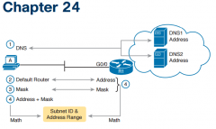
Step 1. Check the host’s list of DNS server addresses against the actual addresses usedby those servers. Step 2. Check the host’s default router settings against the router’s LAN interface configuration,for the ip address command.Step 3. Check the subnet mask used by the router and the host; if they use a differentmask, the subnets will not exactly match, which will cause problems for somehost addresses.Step 4. The host and router should attach to the exact same subnet—same subnet IDand same range of IP addresses. So, use both the router’s and host’s IP addressand mask, calculate the subnet ID and range of addresses, and confirm they arein the same subnet as the subnet implied by the address/mask of the router’s ipaddress command |
|
|
Two root causes of DNS problems |
■ A user host (DNS client) that has an incorrect setting for the DNS server IP address(es) ■ An IP connectivity problem between the user’s host and the correct DNS server |
|
|
Conditions that must be true for DHCP messages to be able to flow from a client to a DHCP server |
Step 1. If using a centralized DHCP server, at least one router on each remote subnetthat has DHCP clients must act as DHCP relay agent, and have a correctly configuredip helper-address address subcommand on the interface connected tothat subnet. Step 2. Troubleshoot for any IP connectivity issues between the DHCP relay agent andthe DHCP server, using the relay agent interface IP address and the server IPaddress as the source and destination of the packets. Step 3. Whether using a local DHCP server or centralized server, troubleshoot for anyLAN issues between the DHCP client and the DHCP relay agent. Step 4. Troubleshoot incorrect server configuration. |
|
|
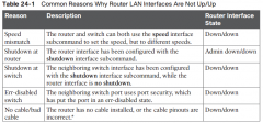
Common reasons why router LAN interfaces are not up/up |
|
|
|
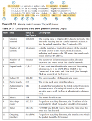
show ip route field reference and explanations |
|
|
|
Types of overlapping IP address configuration issues that IOS can and can't recognize |
Preventing the overlap on a single router: IOS detects the overlap when the ip addresscommand implies an overlap with another ip address command on the same router.Allowing the overlap on different routers: IOS cannot detect an overlap when an ipaddress command overlaps with an ip address command on another router. |
|
|
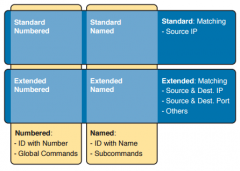
Summary of four main categories of IPv4 ACLs in Cisco IOS |
|
|
|
Summary of first-match logic used by all ACLs |
ACLs use first-match logic. Once a packet matches one line in the ACL, the router takesthe action listed in that line of the ACL, and stops looking further in the ACL. |
|
|
Wildcard mask logic for decimal 0 and 255 |
Decimal 0: The router must compare this octet as normal. Decimal 255: The router ignores this octet, considering it to already match. |
|
|
Wildcard mask logic to match a subnet |
■ Use the subnet number as the source value in the access-list command. ■ Use a wildcard mask found by subtracting the subnet mask from 255.255.255.255 |