![]()
![]()
![]()
Use LEFT and RIGHT arrow keys to navigate between flashcards;
Use UP and DOWN arrow keys to flip the card;
H to show hint;
A reads text to speech;
66 Cards in this Set
- Front
- Back
|
Structural shapes formed by |
Hot rolling |
|
|
Standard views used to illustrate steel structures on drawings |
Plan view, elevation view, section views |
|
|
View looking down on top of structure, multi story building require more views |
Plan view |
|
|
Looking from one side of building. Shows vertical height dimensions |
Elevation view |
|
|
Gives close up detail of part or section of building |
Section views |
|
|
Used to show location of holes, clips, base plates |
Detail drawings |
|
|
Shape for misc. |
M |
|
|
W columns have |
Equal web and flange thicknesses |
|
|
W beams have |
Unequal web and flange thicknesses |
|
|
ST, WT and MT structural tees made by |
Cutting S, W or M shape beams or columns in half |
|
|
Beam/Column designation for W12x20x2 |
W shape with nominal depth of 12 ", weight is 20 lb/ft, piece is 2 feet long |
|
|
Bolt holes on structural members laid out on |
Gage lines |
|
|
Gauge line is |
The distance from the line to the heel of an angle or channel or the centerline of a beam web |
|
|
Holes are spaced in what direction |
Parallel to the length of the member |
|
|
Hole spacing on the gage line |
Pitch |
|
|
3 methods of showing dimensions on a print |
Standard, extension, group |
|
|
Most difficult method of dimensions to read on print |
Group |
|
|
Easiest dimension method to use on drawings |
Extension |
|
|
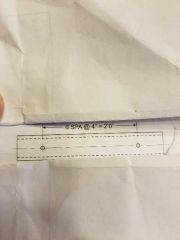
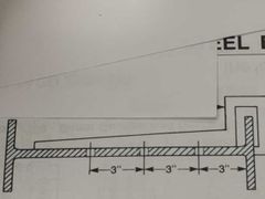
Group dimension |
|
|
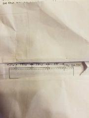
Extension |
|
|
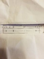
Standard |
|
|
Drawing shows dimensions from hole to hole |
Group |
|
|
Size of heavy hex head on bolt specified to be |
Same as nut |
|
|
Bolt type has shorter thread length to eliminate it from the shear plane |
Structural bolts |
|
|
Snug tight condition |
When all plies of joint are in firm contact |
|
|
Slip critical connection (friction type connection) definition |
Relies on friction between steel plies and high clamp load of structural bolt and nut to prevent movement |
|
|
Connection requires specific torque for given bolt size |
Slip critical connections |
|
|
2 types of bolting methods |
Slip critical and snug tight |
|
|
4 methods of fully tensioning bolts for slip connections |
Turn the nut method, alternative bolts, head indicating washer (DTI), calibrated torque wrench |
|
|
Least favorable of the 4 methods of tightening bolts |
Torque wrench |
|
|
Body of bolt |
Distance from under the head to End of bolt |
|
|
Specific load that a fastener must be tested at without any indication of deformation or failure |
Proof load |
|
|
Larger edge distance required when |
Hole is near sheared edge |
|
|
Steel base plates required when |
Columns bear on concrete footings |
|
|
Sufficient number of anchor bolts to hold verticle columns in base plates |
2 |
|
|
Thickness of base plate should be no less than |
1/5 x the overhang from the column to base plate edge |
|
|
Anchor rods made from what material |
ASTM A36 |
|
|
Seated beam shear designed to support what kind of load |
Vertical only |
|
|
Seated beam shear most commonly used |
At beam to column supports |
|
|
Stiffened thickness must not be less than |
Beam web thickness |
|
|
Min. And max end plate thickness |
6mm min 10 mm max |
|
|
End plate thickness based on |
Minimum edge distance |
|
|
Minimum angle thickness |
6mm |
|
|
Shear connections are for |
Vertical shearing |
|
|
Minimum and maximum clearance between beam and column |
10-20 mm |
|
|
Vertical support members In a structural steel frame |
Columns |
|
|
Horizontal support members inna structural steel frame building. Usually made from wide flange shapes |
Beams |
|
|
Horizontal support members in structural frame used to span between columns in building or between supports in a bridge |
Girders |
|
|
Built up shapes that support roofs and floor systems. Used in place of girders when long spans desired but overall weight is a consideration |
Trusses |
|
|
The thickness of material or parts which the fastener is design to secure when fully assembled |
The Grip |
|
|
Bolt body length is from |
Underside of the head to the last scratch of thread |
|
|
Bolt length |
Length from underside of the head to the extreme end of the bolt |
|
|
Test load which a fastener must withstand without any indication of significant deformation or failure |
Proof load |
|
|
Thread length of a bolt |
From the extreme point of the bolt to the last complete thread |
|
|
Circular boss on the bearing surface of a bolt or nut |
Washer face |
|
|
Shop bolt |
|
|
Countersink near side |
|
|
Countersink far side |
|
|
Open holes |
|

|
Field splice |
|
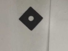
What tool is being used on the beam |
Beam web gauge |
|
|
% of holes in all the joints must have hand tightened bolts or drift pins in place before removing crane |
50% |
|
|
Is dry packing grout acceptable in bearing areas? |
No |
|
|
What is the type of grout used for bearing areas |
Sika 212 flowable grout |
|
|
CSA standard for structural welded steel construction |
W59 |
|
|
CSA standard for welding of steel structures |
W47.1 |