Reading...
![]()
Play button
![]()
Play button
![]()
Use LEFT and RIGHT arrow keys to navigate between flashcards;
Use UP and DOWN arrow keys to flip the card;
H to show hint;
A reads text to speech;
86 Cards in this Set
- Front
- Back
|
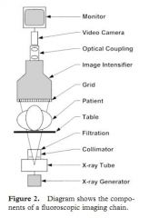
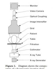
Why is filtration material added to the fluoroscopy machine
|
to attenuate low energy X-rays.
|
|
|
What determines the effectiveness of a filter
|
the HVL (half value layer)
|
|
|
What is the HVL
|
attenuating material that reduces the beam inten-
sity by one-half at a specified kilovolt peak. |
|
|
What is the HVL of a filter at 80 kVp
|
2.3 mm
|
|
|
What if the kVp is greater than 80 kVp
|
it should be increased
|
|
|
What is the most common filtration material
|
aluminum
|
|
|
Besides what other fitration is used for x-ray filtering
|
copper
|
|
|
What are 2 factors that must be considered when designing a table for a flouroscopy machine
|
patient suppurt
not decreasing the attenuation of the x-rays |
|
|
Why is it particularly important not to have much attenuation caused by the table in over table xray tube configurations
|
low attenuation tables decrease radiation dosage
|
|
|
What is a table usually made out of
|
carbon fiber
|
|
|
Why are grids used in flouroscopy
|
Anti-scatter grids are used to improve image con-
trast by reducing the scattered x rays that reach the image receptor. |
|
|
What is the typical grid ratio for a fluoroscopy table
|
The grid
ratios for fluoroscopy range from 6:1 to 10:1, which is generally lower than common radio- graphic grid ratios (8:1 to 16:1) |
|
|
What has a higer grid ratio...fluoro or plain film
|
plain film
|
|
|
Do grids increase the patients exposure to X-ray scatter
|
yes
|
|
|
What is the benefit of an X-ray grid
|
better contrast
|
|
|
Is an X-ray grid always required
|
no
|
|
|
When should the grid be removed
|
if there is not going to be alot of scatter
|
|
|
When is a grid not needed
|
a
grid is not needed if a large air gap between the patient and the image intensifier is required for geometric magnification, access to the patient, or access to interventional devices |
|
|
How much can patient exposture be reduced if the grid is removed
|
up to 50%
|
|
|
Is removing the grid always feasible
|
depends on the machine. Sometimes it is easy and sometimes not.
|
|
|
Where is an X-ray grid located
|
just below the image intensifier
|
|
|
If the patients body part is small or if there is a small field of view what happens to the contrast
|
it is improved. (might consider no grid)
|
|
|
If the image intensifier is widely seperated from the patient is there need for a grid
|
no
|
|
|
What does an image intensifier do
|
The image intensifier converts incident x rays
into a minified visible light image and, in the pro- cess, amplifies the image brightness by about 10,000 times for better visibility to the viewer. |
|
|
What are the major components of the image intensifier
|
input layer
anode output layer |
|
|
What is the input layer
|
converts X-rays to electrons
|
|
|
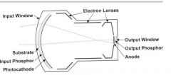
What is the input layer made of
|
The input layer is made up of four different
components: the input window, substrate, input phosphor, and photocathode. |
|
|
What does the input layer look like
|
|
|
|
What is the purpose of the electron lense
(this is a main part and was left out of the previous card) |
electron lenses to focus the electrons
|
|
|
What does the anode do
|
accelerates the electrons
|
|
|
What do the electron lense and anode look like
|

|
|
|
What is the function of the output layer
|
them, and an output layer to
convert them into a visible image |
|
|
Are all the components of the image intensifier in an evacuated bottle
|
yes
|
|
|
What is the path of the x-ray as it moves through the input layer
|
irst, x rays strike
the input window, which is made of a curved, thin layer of metal or glass. Next, they pass through the 0.5-mm-thick aluminum substrate layer and input phosphor layer, where they are converted into light photons. |
|
|
What happens to the light photons as they travel to the photocathode
|
The light pho-
tons emitted from the input phosphor are then absorbed in the photocathode and converted into electrons. |
|
|
What is the input phosphorus made of
|
cesium iodide
|
|
|
What happens to the electrons after they emerge from the photocathode
|
they are accelerated through a vacuum to the output layer by the electon optic system
|
|
|
What does the electrons optic system do
|
it accelerates the electrons to the output layer
|
|
|
What makes up the electron optics system
|
three charged electrodes and an anode plate at the output layer
|
|
|
How does the electron optic system do
|
hese components create an electric potential,
which intensifies and demagnifies the electron beam to the size of the small output layer |
|
|
What happens to the electrons at the output phosphorus
|
At the output phosphor, the electrons are converted into
visible light photons. |
|
|
What happens to the light photons after the output phosphorus
|
These photons are then
transmitted out of the image intensifier through a glass output window. |
|
|
What happens as a result of the acceleration of the electrons and minification of the image
|
the illumniation level of the output image compared to the input is greatly increased
|
|
|
What is the illumination level known as
|
brightness gain and ranges from 5k to 20k
|
|
|
What are the typical input window size for image intensifiers
|
Image intensifiers are available with different
diameter input windows of 10-40cm |
|
|
What determines the size of the input windo
|
The selec-
tion of the diameter depends on the maximum FOV requirements of the clinical application. |
|
|
What does size of the image output window do
|
adjust to field of view
|
|
|
What occurs in the magnificaiton mode
|
In magnifica-
tion mode, the central circular area of the input layer is focused onto the full output layer by ad- justing the voltage of the electron optics electrodes. |
|
|
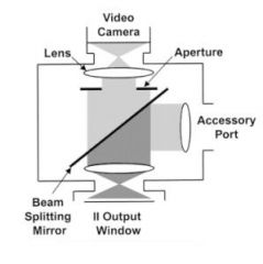
What is the function of the optical coupling system
|
The optical coupling system distributes light
from the image intensifier output window to a video camera and other image recording devices |
|
|
Where is the optic coupling system located
|
|
|
|
What does the optic coupling system look like
|
|
|
|
What is the reason for a partially silverd mirror
|
to spit the light beam and directs a portion of the light from the image intensifier output window to an accessory device
for image recording and passes the remainder to the video camera. |
|
|
What does the beam splitting mirror look like
|

note some of the light going to the accessory port and some to the video camera
|
|
|
Where is the optical coupling system aperture located
|

|
|
|
What is the reason for the circular aperture
|
A circular aperture is also in-
cluded to set the proper light level required by the video camera. The aperture setting affects the appearance of noise in the fluoroscopic image. |
|
|
How do the circular aperture and the ABC system work together
|
When the aperture is set to a small size, much of
the light from the output window is blocked from reaching the video camera. As a result, the ABC system increases the radiation exposure to main- tain the light level at the camera, producing a fluoroscopic image with low noise. |
|
|
What happens when the aperture is wide open
|
the radiation exposure is low and there is more image noise
|
|
|
What happens when the aperature is small
|
there is more radiation and less noise
|
|
|
What is the advantage of having an analog to digital coverter
|
digital information can ct processed
|
|
|
What part of the video camera recieves the signal from the optic coupling lens
|
a 2.5 cm photoconductive target
|
|
|
What is contained in the vacuum tube cylinder
|
a photoconductive target and a scanning beam
|
|
|
What part of the video camera recieves the signal from the optic coupling lens
|
a 2.5 cm photoconductive target
|
|
|
What is contained in the vacuum tube cylinder
|
a photoconductive target and a scanning beam
|
|
|
What does the vacuum tube of the video camera look like
|
|
|
|
What signal is hitting the photoconductive surface of the video camera
|
light
|
|
|
What happens to light as it focuses on the photoconductive layer of the video camera
|
he optical coupling lens focuses
the image intensifier output image onto the tar- get, forming a latent charge image from the charge carriers within the photoconductive layer. |
|
|
Where is the electron beam in the vacuum tube of the video camera
|

|
|
|
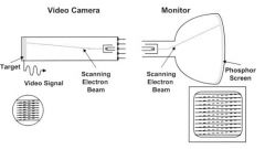
How does the electron beam work
|
This latent image is read out by the electron
beam, which scans across the target in a series of horizontal raster lines |
|
|
What is the horizontal raster scanning pattern
|

bottom left
|
|
|
What is raster scanning
|
raster scanning, is the rectangular pattern of image capture and reconstruction in television
|
|
|
What happens as the scanning electron beam moves across the target
|
As the scanning electron
beam moves across the target, a current signal is produced that represents the two-dimensional image as a continuous series of raster lines with varying voltage levels |
|
|
What is a charge coupled device camera
|
Charge coupled de-
vice (CCD) cameras consist of a solid-state array of light sensors, which store the image as pixels until they are read out as voltage pulses repre- senting the two-dimensional image |
|
|
What are the advantages of CCDs
|
Compared
with traditional video cameras, CCD cameras are smaller, are more rugged, require less power, and have a longer lifetime. |
|
|
What are some additonal devices that a flouroscopy machine may have to record images
5 |
spot film de-
vices, film changers, photospot cameras, cine cameras, and digital photospots |
|
|
What are spot film devices
|
Spot film devices are used to acquire a radio-
graphic image with a screen-film cassette that is moved into position in front of the image intensi fier |
|
|
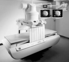
What does an under the table Xray tube RF system look like
|
|
|
|
What is a film changer
|
these acquire radiographic film either in front of the image intensifier or with it move out of position
|
|
|
What are some alternative names of a film changer
|
rapid film changer, se-
rial film changer, cut-film changer, Puck |
|
|
How does a film changer work
|
Films are moved rapidly
into position from a supply magazine at a select- able rate up to four films per second and then transferred to a take-up magazine for manual transport to a film processor. |
|
|
How fast can a film changer wokr
|
4 films a second
|
|
|
What does the photospot camera do
|
Photospot cameras record the image intensi-
fier output on rolled or cut film to produce im- ages about 10 cm in diameter. |
|
|
Where is the photospot camera mounted
|
on the optical distributor ac-
cessory device port to record images rapidly dur ing the fluoroscopic examination. |
|
|
What is a photospot film used for
|
Photofluorog-
raphy is generally used for the same clinical ex- aminations as spot film devices |
|
|
A cine camera
may also be mounted as an accessory image re- cording device to acquire images on 35-mm film. Cinefluorography is typically used for cardiac catheterization procedures to record rapid rate images of the beating heart |
yes
|
|
|
What have all of the imaging methods i just wasted my time making cards for been replaced by
|
Digital photospots are acquired by re-
cording a digitized video signal and storing it in computer memory. The operation is fast and convenient, plus image quality can be enhanced by the application of various image processing techniques, including window-level, frame aver- aging, and edge enhancement. However, the spa- tial resolution of digital photospots is less than that of film images |
|
|
What is a RF table
|
radiography/flouroscopy table
|