Reading...
![]()
Play button
![]()
Play button
![]()
Use LEFT and RIGHT arrow keys to navigate between flashcards;
Use UP and DOWN arrow keys to flip the card;
H to show hint;
A reads text to speech;
160 Cards in this Set
- Front
- Back
|
P-3 can be fueled by what methods
|
- pressure fueling under the wing
- gravity feed (except tank 5) (NATOPS 2.10.1) |
|
|
P-3 can be defueled by what methods
|
- pressure defueling under the wing
- fuel dump from tank 5 (NATOPS 2.10.1) |
|
|
pressure fueling panel is located
|
inboard aft section of starboard wing
(NATOPS 2.10.1.4) |
|
|
what happens when refueling panel system power switch is turned on
|
- solenoid holds it on
- transfers power of fueling valves from flight station to refueling panel - illuminates reset light in flight station - prepares to test pilot valves (NATOPS 2.10.1.8.1) |
|
|
lights on the refueling panel are powered by
|
MDC
(NATOPS 2.10.1.8) |
|
|
how many transfer and pressure fueling valves are there and where can they be controlled from
|
- 6 pressure fueling valves (one in each tank); all controlled on fueling panel outside
- 4 of these (in wing tanks) are also transfer valves; all controlled on fuel panel in flight station also (NATOPS 2.10.1.4) |
|
|
refueling panel system power switch power source
|
MDC
(NATOPS 2.10.1.8.1) |
|
|
fuel quantity gauges (refueling panel) power source
|
Bus A
|
|
|
when refueling, pressurized fuel flows through the same valves used for ___ (only on which tanks)
|
- transfer valves
- wing tanks only, not tank 5 (NATOPS 2.10.1.4) |
|
|
refueling panel system check switch does what (under what conditions)
|
- if switched to PRIMARY or SECONDARY, each tank's pri/sec pilot valve test solenoid is energized
- when these solenoids are energized and pressure fueling is hooked up, full tank condition is simulated to see if fuel cuts off (NATOPS 2.10.1.8.2) |
|
|
warning about pressure refueling / over-pressurization indicator
|
if the black pointer contacts the over-pressure indication line on the tank 5 pressure gauge, stop fueling and ensure visual inspection of both sections of tank 5 prior to flight
(NATOPS 2.10.1.9) |
|
|
draw out how primary / secondary poppets work
- tanks full - test |
see PJA Fig 2-1
|
|
|
what protects each tank from over-pressurization due to refueling / transfer
|
1/4: larger diameter vent line allows fuel to vent overboard (inspection if fuel spills from wing tips during refueling)
2/3: recirculation valve and tube vents excess back to tank 5 center section 5: over-pressurization gauge next to refueling panel sticks at highest pressure (inspection if black pointer touches the overpressure indication line) (PJA 2.3.2) |
|
|
during refueling, primary and secondary poppets are tested when
|
- when beginning fueling
- when approx 85% full (PJA 2.4) |
|
|
ensure fueling pressure does not exceed...
|
55 psi
|
|
|
can you take a full load of fuel using gravity feed fueling method only
|
can't fill tank 5
|
|
|
center-point pressure refueling rate
|
300 gpm per truck (up to 2)
|
|
|
use of radios during fueling
|
Warning: Use of transmitting equipment during fueling operations should be avoided.
|
|
|
when is fuel quantity verification required
|
all preflights
|
|
|
fuel quantity verification methods
- order of most accurate - fuel each method is calibrated for - fuel level required for each method |
(1) density vs. quantity
- used for any fuel type - full tank required (2) dipstick - calibrated in gallons - requires 5500 lbs inboard, 9500 lbs outboard (normal ramp load) (3) hydrostatic - calibrated for JP-5 - not within 500 lbs of being full (4) tank 5 sight gauge - calibrated for JP-4 - need >4,300 lbs |
|
|
fuel dip gives a value in [pounds, gallons, etc.]
|
gallons (multiply by density)
|
|
|
does pitch affect hydrostatic reading? roll?
|
- based on 0 deg roll, 1 deg nose down
- roll affects more than pitch (NATOPS 2.10.1.13) |
|
|
how to use the tank 5 sight gauge
|
- hinged panel on underside of fuselage
- lower it until the prism image is dark - read fuel level off calibrated scale (NATOPS 2.10.1.12) |
|
|
fuel samples are good for...
|
24 hours
|
|
|
on fuel sample page in the ADB, you want to see what code
|
1A
first sample, all clear |
|
|
what does the reset button do on the fuel panel in the flight station
|
if fueling panel has command of the fueling valves (indicated by the RESET light being on), press the reset button to regain control in the flight station (NATOPS 11-7)
|
|
|
fuel dump valve power source
|
MDC
|
|
|
fuel dump pump power source
|
Bus A / MDC
|
|
|
fuel dump airspeed
|
140 - 300 kts
(NATOPS 15.8.4) |
|
|
fuel dump altitude
|
- min 6000 AGL unless weather or emergency requires lower, then avoid populated areas
- if under positive control you should notify ATC that you will be dumping fuel (OPNAVINST 3710.7 - 5.5.6) |
|
|
flap position for fuel dumping
|
- not recommended past the UP position
- WARNING: prohibited with flaps past the APPROACH position (NATOPS 4.11) |
|
|
normal rate of fuel dump
|
approx 1000 lbs / min with dump pump and both transfer valves (PJA 2.6)
|
|
|
turning on the dump switch does what
|
- dump valve open
- dump pump on - transfer pumps on (NATOPS 2.10.1.7.1) |
|
|
dump pump is in which tank
|
center section tank (NATOPS 2.10.1.7)
|
|
|
how does fuel get out of each of the sections of tank 5 during fuel dumping
|
dump pump - center section
transfer pumps - fuselage section (PJA 2.6) |
|
|
when dumping fuel, you should close ___ because...
|
- wing transfer valves
- transfer pumps are running automatically so you ant them pushing fuel out instead of into the wing tanks (NATOPS 2.10.1.7) |
|
|
considerations for fuel dump with no good transfer pumps
|
- can only dump from center section tank
- up to 6 deg nose high may drain some of remaining 2000 lbs past the ball check valve if ZFW is exceeded: - do not exceed 2.1g - avoid turbulent air penetration - abort the mission - land |
|
|
possible causes of fuel dumping slower than expected
|
- dump valve control relay energized (valve open, transfer pumps on) but dump pump control relay not energized (no dump pump)
- dump pump CB out (Bus A / MDC) - lost Bus A - transfer pump CB out (power only, Bus A or Bus B; control power provided from fuel dump control) (PJA 2.6) |
|
|
fuel log requirements
|
- shall always compute fuel requirements hourly
- fuel log required --> scheduled for 500 nm from nearest suitable landing field --> scheduled for more than 6 hours duration --> fuel quantity indicator malfunction - fuel log entries either hourly or in 5,000 lb increments |
|
|
capacity (gallons) of fuel tanks
|
1 & 4: 1606 gal
2 & 3: 1671 gal 5: 2646 gal total: 9200 gallons (NATOPS ch. 3) |
|
|
purpose of foam in fuel tanks (AFC-517)
|
explosion suppressant protecting against incendiary or tracer rounds (NATOPS 2.10.1.2)
|
|
|
explain the different purposes of the emergency shutoff valve and the main tank valve (in the fuel tank, not the FCU)
|
ESV - stops fuel flow to that engine (can still crossfeed out)
MTV - stops fuel flow to / from that tank (can still crossfeed to the engine) (NATOPS FO-11) |
|
|
main tank valve power source
|
MEAC
|
|
|
when do you close main tank valves
|
WARNING: If a wing tank is empty its main tank valve shall be closed.
(NATOPS 8.32) |
|
|
how many fuel probes are in each tank
|
outboard tanks: 5 each
inboard tanks: 3 each tank 5 center section: 2 tank 5 fuselage section: 1 total: 19 (FEJA 2.7) |
|
|
fuel totalizer power source
|
MEAC
|
|
|
fuel quantity gauges (flight station) power source
|
MEAC
|
|
|
fuel gauges test switch power source
|
EMDC
|
|
|
fuel gauge test switch does what
|
drives indicators toward zero
(NATOPS 2.10.1.10.15) |
|
|
when testing the fuel gauges
|
Caution: don't let them go all the way to zero
(NATOPS 15.8.1) |
|
|
stuck fuel quantity indicator (with 2 notes/warnings/cautions)
|
1. TEST (not all the way to zero)
2. TAP the gauge 3. CHECK the CBs (MEAC; do not reset) 4. fuel log 5. no more troubleshooting (NATOPS 15.8.1) |
|
|
if a fuel ___ CB trips, do not reset it
|
Warning: fuel quantity indicator
(NATOPS 15.8.1) |
|
|
if fuel quantity begins to drive toward zero...
|
Note: pull fuel quantity system test CB on EMDC
(NATOPS 15.8.1.1) |
|
|
if fuel quantity indicator goes off scale or fluctuates abnormally
|
1. Pull both CBs (MEAC and Bus A)
2. fuel log 3. no more troubleshooting (NATOPS 15.8.1.2) |
|
|
what keeps fuel from spilling out the vents
|
float operated valves close when it senses tank is full (actually full or just in a turn)
(PJA 2.3) |
|
|
how does the tank 5 vent system differ from wing tanks? why?
|
- ram air scoop under left wing forces air into the bladder tank
- circulates, then exits through the wingtip vent - restrictor keeps backpressure in the tank - bladder section is in unpressurized section of fuselage, so this keeps it from collapsing (PJA 2.3.1) |
|
|
why is one tank vent bigger than the others
|
tanks 1 & 4 have larger diameter so fuel can spill overboard to prevent overpressurization during refueling / transfer
(PJA 2.3.2) |
|
|
what is the purpose of the surge box
|
- keeps boost pump submerged in fuel for cooling and to prevent cavitation
- when tank is low on fuel, it collects what's left and keeps in near the boost pump (PJA 2.2) |
|
|
how does fuel get into the surge box
|
- flapper valve
- over the top of the box - scavenge pump |
|
|
normal boost pump pressure
|
15 - 30 psi
(NATOPS 2.10.1.3) |
|
|
purpose of the two sections of the boost pump
|
scavenge - discharges into the surge box
boost - pups fuel from surge box to engine driven pump, crossfeed system (NATOPS 2.10.1.3) |
|
|
thermal switch in the boost pumps and transfer pumps does what
|
disconnects it whenever the case temperature of the pump becomes excessive (NATOPS 2.10.1.5.1, NATOPS 2.10.1.3)
|
|
|
how to check boost pump pressure
|
use crossfeed pressure gauge with only one crossfeed valve open and the same boost pump on
(NATOPS 2.10.1.10.12) |
|
|
three lights on the fuel panel caused by low fuel pressure and the psi limit that causes them
|
2 for 4, 4 for 2
2 transfer pumps - PRESS LOW - <4 psi 4 electric boost pumps (tanks) - BOOST - <2 psi also 4 engine-driven boost pumps (engine) - PRESS LOW - <19 psi differential |
|
|
fuel boost pumps power sources
|
1 - Bus A / EMDC
2 - Bus B / EMDC 3 - Bus A / EMDC 4 - Bus B / EMDC |
|
|
boost pump setup for takeoff
|
all shall be on for takeoff
|
|
|
boost pump failure in climb
|
1. verify pump failure & establish crossfeed
2. inop boost pump - OFF 3. boost pump CONT CB - Pull 4. continue climb 5. after sufficient time at cruise, stop crossfeed; if ok, continue mission, if not... 6. return to crossfeed 7. wait several minutes, then repeat step 5 Note: adjust mission (time, altitude) as necessary (NATOPS 15.8.2.1) |
|
|
"verify pump failure" means...
|
- check on crossfeed gauge
- check CBs |
|
|
boost pump failure in cruise / descent
|
1. verify pump failure
2. inop boost pump - OFF 3. boost pump CONT CB - Pull 4. monitor engine operation 5. if abnormal, crossfeed, then after sufficient time at cruise, stop crossfeed; if ok, continue mission, if not... 6. return to crossfeed 7. wait several minutes, then repeat step 5 Note: if low on fuel with inop boost pump, avoid nose down / yaw Note: if prolonged or high rate of descent is required, crossfeed (NATOPS 15.8.2.2) |
|
|
when should you avoid nose down / yaw (fuel related)
|
- if low on fuel and boost pump is inop
- fuel can't get over the walls of the surge box and scavenge section not available to pump fuel into the surge box (NATOPS 15.8.2.2) |
|
|
if boost pump is inop, on descent...
|
establish crossfeed if prolonged or high rate of descent is required (NATOPS 15.8.2.2)
|
|
|
if boost pump is inop, how does fuel get
- into the surge box - to the engine from the surge box |
- gravity flow through the flapper check valve or splash over the top
- engine driven boost pump can suction feed through a bypass line from the surge box (PJA 2.2) |
|
|
if the electrical boost pump fails, the ___ has enough suction to draw fuel from the wing tank
|
engine driven boost pump
(PJA 3.2.2) |
|
|
if a boost pump fails in the climb (___ light on), fuel starvation should occur (when?), unless
|
- PRESS LOW light
- 1000 ft higher - unless crossfeed is established (PJA 3.2.2) |
|
|
if the engine driven boost pump fails...
|
engine operation should continue as long as the tank boost pump operates normally
(PJA 3.2.2) |
|
|
relationship between fuel aeration and
- altitude - BOOST light - PRESS LOW light - flameout |
- air bubbles form in fuel as altitude increases
- doesn't affect fuel boost pump - will affect engine driven boost pump if fuel boost pump is off / no crossfeed and aircraft is climbing; gradual power loss begins around 13,000 ft - if no boost pump / crossfeed, flameout will occur if climb is continued |
|
|
fuel PRESS LOW light on taxi
|
treat it like you are in the air (not a stuck pressure switch, something is probably wrong)
|
|
|
reset boost pump CBs?
|
power - no
control - yes |
|
|
- when will fuel be stuck in the tank
- when do you go home vs. continue |
Emergency Shutdown with fuel boost pump failure in the same tank (or crossfeed valve stuck closed)
Boost pump - go home (stuck fuel, and you are one engine-driven boost pump failure away from a flameout) Crossfeed valve - local - continue - overland repo - continue with close diverts; push up 1 & 4, pull back 2 & 3 to burn more fuel from bad tank (if problem is on 1 or 4, opposite for 2 & 3) - over water / mission - go home unless you would be ok losing the engine right now (3 engine go home gas using the other tank's quantity and max fuel imbalance) |
|
|
which cells are the tank 5 transfer pumps in? the tank 5 refueling valves?
|
transfer pumps - both in bladder / fuselage tank
refueling valves - one in each cell of tank 5 (NATOPS 2.10.1.5.1) |
|
|
ball check valve keeps tank 5 fuel in the ___ section if __ deg nose up/down
|
keeps in fuselage tank if >6 deg nose high (PJA 2.5)
|
|
|
fuel flows through the interconnect from the center section to the fuselage section if the center section has >___ lbs (tank 5 > ___ lbs)
|
center section: 2000 lbs
tank 5: 4000 lbs (PJA 2.5) |
|
|
what is the purpose of the ball check valve in the tank 5 interconnect line
|
keeps fuel in the fuselage tank above 6 deg nose high so transfer pumps don't cavitate (PJA 2.5)
|
|
|
name the two parts of tank 5; which is father forward, which is bladder or not
|
forward:
- fuselage tank - bladder type aft: - center section tank - integral type |
|
|
fuel transfer requires how many transfer pumps
|
1, but 2 used normally (NATOPS 2.10.1.5)
|
|
|
how do you stop fuel from transferring to a specific tank
|
close the transfer valve (NATOPS 2.10.1.5)
|
|
|
two sections of transfer pumps do what
|
scavenge - pumps fuel to the fuselage cell from the bottom of the center section tank
boost section - pumps fuel from fuselage cell to any wing tank (NATOPS 2.10.1.5.1) |
|
|
how does the output pressure of the scavenge vs booster section of the transfer pumps compare
|
booster - 5000 lbs/hr
scavenge - 2000 lbs/hr booster puts out twice as much as scavenge (PJA 2.5) |
|
|
fuel transfer valves power source
|
MDC
|
|
|
transfer pumps power sources
|
forward: Bus A / EMDC
aft: Bus B / EMDC |
|
|
if transfer pumps are running and wing tank transfer valves are closed...
|
fuel returns to the fuselage tank through the pressure relief valves (one per transfer pump)
(PJA 2.5) |
|
|
after start checklist - fuel transfer
|
turn on both transfer pumps and open all transfer valves (PJA 2.5.1)
|
|
|
transfer pump PRESS LOW light
|
shut off the pump and refer to NATOPS if fuel remains in tank 5
(NATOPS 11-7) |
|
|
single transfer pump failure
|
1. transfer pump switch - OFF (inop)
2. transfer pump CBs - PULL (both) 3. transfer with remaining pump to 3000 lbs in tank 5 4. close transfer valves; burn 250 lbs from each wing tank 5. open transfer valves; lower tank 5 level by 1000 lbs 6. repeat 4 & 5 until tank 5 is empty Note: use nose down to get all fuel out of center section tank (NATOPS 15.8.3) |
|
|
failure of both transfer pumps
|
1. turn off both pumps
2. pull all transfer pump CBs (2 each) 3. determine ZFW (add tank 5 fuel) 4. if max ZFW not exceeded, adjust mission for less fuel 5. if max ZFW exceeded: - dump fuel until below ZFW - if still above ZFW (1) do not exceed 2.1g (2) avoid turbulent air penetration (3) abort the mission (4) land (NATOPS 15.8.3) |
|
|
why do we pull both CBs for transfer pump failure instead of just control CB like for a boost pump failure
|
so dumping fuel won't energize it (dump control relay is different from the normal pump control relay)
|
|
|
if max ZFW is exceeded
|
(1) do not exceed 2.1g
(2) avoid turbulent air penetration (3) abort the mission (4) land (NATOPS 15.8.3) |
|
|
when would tank 5 fuel count in your ZFW
|
if wing tanks were not full (NATOPS 4.9.1)
|
|
|
max zero fuel weight
|
80,400 lbs (no AFC-517)
82,400 lbs (AFC-517) - varies due to extra generators, stores (NATOPS 4.9.1) |
|
|
the crossfeed crossship valve is located where
|
in tank 2 (PJA 3.2.3)
|
|
|
fuel crossfeed pressure indicator power source
|
Inst Bus 2
|
|
|
crossfeed valves power sources
|
MEAC
|
|
|
crossfeed system can pump fuel from one tank to ___ or ___, but not to ___
|
to engines or crossfeed manifold but not into another tank (NATOPS 2.10.1.6)
|
|
|
crossfeed procedure (w/ warning)
|
1. fuel boost pumps - ON
2. crossfeed valve - OPEN (supplying tank) 3. check pressure 15-30 psi (open cross-ship if necessary) 4. crossfeed valve - OPEN (receiving engine) 5. fuel boost pump - OFF (receiving engine) Warning: if supplying tank goes empty or its boost pump fails, you may flameout both engines, so be careful if less than 2000 lbs in tank; close main tank valve if tank is empty (NATOPS 8.32) |
|
|
how to set up crossfeed to stay under the min fuel for flight line in figure 4-4
|
- start off crossfeeding from inboards
- once inboards drop to 8k, crossfeed from outboards - once they are balanced, crossfeed as required to keep them balanced |
|
|
what if crossfeed pressure gauge indicates pressure with crossfeed valves closed?
------- ------- up to what pressure? why is this ok? |
may indicate up to 50 psi with valves closed due to thermal expansion; excessive pressure relieves into tank 5 (NATOPS 2.10.1.10.12)
|
|
|
- TANK shutoff valve lights on
- XFEED valve lights on - cross-ship XFEED light on |
valve position does not coincide with the switch position (NATOPS 11-6)
|
|
|
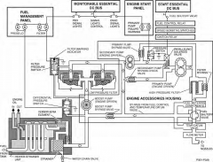
what path does the fuel take from the tanks to the engine
|
- tanks
- fuel heater / strainer - engine driven boost pump - low pressure filters (two in parallel) - primary and secondary engine driven pumps (series or parallel) - high pressure fuel filter - fuel control / fuel shutoff valve - TD valve - fuel flow meter - fuel manifold - fuel nozzles (NATOPS 2.10.2, fig 2-31) |
|
|
what does the fuel heater / strainer do
|
- heats fuel using engine oil heat
- removes water droplets and ice crystals (NATOPS 2.10.2.1) |
|
|
the fuel heater / strainer uses ___ to keep ___ temperature at ___ deg
|
uses oil to keep fuel temp at 40-70 F
(PJA 3.2.1) |
|
|
how does the fuel PRESS LOW light work
|
- differential pressure switch measures pressure on both sides of the engine driven boost pump
- if pump fails, backpressure connects the switch, causing the light to come on (NATOPS 2.10.2.2) |
|
|
fuel PRESS LOW light on
|
Cause:
- differential pressure across the engine driven centrigugal boost pump is low - flickering light indicates a partial obstruction of the fuel line - NOTE: should be out by LOW RPM - After start, possible faulty or stuck pressure switch Action: - Check (1) fuel flow, (2) fuel quantity, (3) engine operating normally, (4) visible fuel on nacelle - in flight: if no fuel visible, continue operation, observing engine closely - during ground operations, if no fuel is visible, cycle respective boost pump or shift engine to normal rpm then back to low rpm; if light goes out and remains out, continue operation (NATOPS 11-6) |
|
|
how does the FUEL FILTER light work
|
- differential pressure switch measures pressure on either side of the filters
- clogged filter causes backpressure, which connects the switch, causing the light to come on (NATOPS 2.10.2.3) |
|
|
FILTER light
|
Cause:
- one or both of the low pressure fuel filters are restricting flow Action: - if engine continues to function normally, continue engine operation (NATOPS 11-6) |
|
|
during normal ops, the pri / sec pumps operate in [parallel / series]
|
series (NATOPS 2.10.2.4)
|
|
|
when and why do the primary & secondary pumps work in parallel
|
- during starts from 16-65%
- to provide sufficient fuel flow at low rpm (NATOPS 2.10.2.4) |
|
|
when happens if a primary or secondary pump fails (will engine still run?)
|
the other will provide sufficient flow to run the engine (NATOPS 2.10.2.4)
|
|
|
the capacity of the [primary / secondary] pump is __% greater than the [primary / secondary] pump...why?
|
- primary is 10% more than secondary
- after 65% on start, primary pump sucks out the backpressure between the two pumps, allowing the paralleling light to extinguish (NATOPS 2.10.2.4) |
|
|
draw out primary & secondary fuel pump operation during starts
|
|
|
|
in the fuel system, ___ are all driven by a common shaft
|
- engine driven boost pump
- primary pump - secondary pump (PJA 3.2.2) |
|
|
where is fuel cut off
- electrically - mechanically |
both at the FCU (NATOPS 2.10.2.6)
|
|
|
how is the fuel shutoff valve close
|
electrically
- fuel and ignition switch to OFF - feather button in mechanically - E handle pulled (*emergency shutoff valve in the fuel tank is also closed mechanically) (PJA 3.5) |
|
|
list the inputs to the FCU
|
- compressor inlet pressure
- compressor inlet temperature - engine speed (rpm) - power lever position (not T.I.T. --> that's the TDs) (NATOPS 2.10.2.6) |
|
|
where is the fuel shutoff valve that the speed sense control opens at 16%
|
FCU (NATOPS 2.10.2.6)
|
|
|
the FCU will add fuel to maintain engine speed of...
|
> 97% (NATOPS 2.10.2.6)
|
|
|
when the fuel shutoff valve is closed, where does the fuel go
|
back to the inlet of the secondary pump (PJA 3.3)
|
|
|
low rpm solenoid power source
|
EMDC (NATOPS fig 2-6)
|
|
|
engines auto shift to normal rpm if coordinator is advanced past ___
|
36 deg (NATOPS 2.9.8.1)
|
|
|
the FCU controls engine speed when?
|
- low rpm - resets fuel topping governor to maintain 71.0 - 73.8%
- power levers in beta range - overspeeds above 104.2 (up to 106.7%) - underspeeds below 97% *also controls fuel flow (not rpm) with TD in NULL (PJA 3.4) |
|
|
what is unique about how the fuel is cut off electrically; why do we care
|
- fuel control relay (in main load center) is energized in order to cut off fuel
- FOUO in MLC when you shut down an engine may be this relay (restart to secure power to it) (FEJA fig 2-5) |
|
|
the FCU performs these functions
|
1. coordinates power with blade angle and engine speed
2. compensates for air density changes (CIP, CIT) 3. prevents excessive T.I.T. during acceleration 4. prevents flameout during deceleration 5. controls rpm in range 104.2 to 106.7% 6. controls prop speed in reverse, low, normal, overspeed 7. provides start fuel flow to prevent overtemp 8. cuts off fuel electrically and mechanically 9. maintains engine speed above 97% |
|
|
the ___ schedules fuel output to the ___ at __% of engine fuel requirements; why?
|
- FCU to TD valve
- 120% - so the TD can add fuel if necessary (NATOPS 2.10.2.6) |
|
|
where does the excess fuel from the FCU and the TD go?
|
both back to the secondary pump inlet
(NATOPS fig 2-31, PJA 3.3) |
|
|
in NULL, the TD valve bypasses __% of the fuel provided by the FCU
|
20%
(0% take, 0% put, FCU providing 120% (FEJA 3.6) |
|
|
why does the FCU provide the TD with __% more than needed when the TD max put is __%
|
FCU --> TD ... 20% more
TD max put ... 15% * other 5% used by TD valve for lubrication and hydraulic operation (FEJA 3.6.1) |
|
|
identify the TD modes and
- when they happen - take limit - put limit - T.I.T. limit |
start limiting (<94% rpm)
- 50% take - 0% put - 830 T.I.T. temp limiting (>94% rpm, <66 deg coordinator) - 20% take - 0% put - 1077 T.I.T. temp controlling (>94%, >66 deg coordinator) - 20% take - 15% put - 1077 T.I.T. |
|
|
explain start limiting TD
- when - purpose - how |
- when rpm is <94%
- keeps T.I.T. <830 C - TD valve in NULL position until 819 T.I.T.; TD valve takes up to 50% to keep T.I.T. below 830 C (FEJA 3.6.1) |
|
|
explain temp limiting TD
- when - purpose - how |
- rpm >94% and coordinator <66 deg
- keeps T.I.T. below 1077 C - TD valve in NULL position until T.I.T. reaches 1077 C; TD valve takes up to 20% to keep T.I.T. below 1077 C (FEJA 3.6.1) |
|
|
explain temp controlling TD mode
- when - purpose - how |
- rpm >94% and coordinator >66 deg
- set predetermined T.I.T. for given coordinator position - TD valve will take up to 20% or put up to 15% to set T.I.T.; ranges from 899 C at 66 deg coordinator to 1083 C at 90 deg coordinator (FEJA 3.6.1) |
|
|
if you lose SEDC with ___, TDs will automatically...
|
- with MEAC powered
- shifts to temp controlling mode (FEJA 3.6.1) |
|
|
what happens if you lose SEDC, forget to cycle the TD after regaining it, then try to start the engine? why?1
|
- TD goes to temp controlling when you lose SEDC with MEAC still powered, which opens the TD valve all the way to try to set 566 deg at ground start power lever position (T.I.T. is currently near 0 deg due to the engine being off)
- when you get SEDC back, TD goes back to start limiting, which leaves the valve in the CURRENT position until 819 T.I.T. - probably will get a hot start (because valve is positioned for 15% put and TD can't catch it in time) (FEJA 3.6.1) |
|
|
what happens if you start an engine with the TD CB (on ___) popped
|
- on SEDC
- TD goes to temp controlling when you lose SEDC with MEAC still powered, which opens the TD valve all the way to try to set 566 deg at ground start power lever position (T.I.T. is currently near 0 deg due to the engine being off) - probably will get a hot start (because 15% more fuel is used than normal and TD can't catch it in time), followed by a stalled / stagnated start (because TD takes 20% to try to get T.I.T. back down to 566 deg) (FEJA 3.6.1) |
|
|
how do the fuel flow meters work
|
- an impeller causes the fuel to swirl
- swirling fuel causes a turbine to displace against spring pressure - this displacement is measured and indicated on the gauge in pph (PJA 3.8) |
|
|
how many fuel flow gauge CBs are there
|
one CB powers all four gauges (NATOPS 2.9.12.4)
|
|
|
fuel flow power supply power source and location
|
Bus A, main load center
|
|
|
how many fuel nozzles are in each engine
|
six (NATOPS 2.10.2.10)
|
|
|
fuel leak
|
emergency shutdown
Warning: if fire or fuel leak - close crossfeed valve... - turn off boost pump... - don't crossfeed from that tank... ...until you know it isn't a fire hazard (NATOPS 15.5.1) |
|
|
go / no-go:
failed - engine driven boost pump - primary pump - secondary pump - fuel boost pump |
all no-go
first 3: - all on the same assembly, so they may all fail fuel BP: - fuel stuck in tank if emergency shutdown will cause imbalance - one pump failure away from a flameout |
|
|
how to handle a dripping or running fuel leak on preflight
|
shall be repaired prior to flight (specific definitions of dripping or running)
|
|
|
when does the enrichment solenoid deenergize (using prime)
|
50 psi fuel pressure or 65% rpm, whichever comes first
|
|
|
on start, at ___, the paralleling light should go out
|
65%
|
|
|
fuel primer is primarily designed to...
|
provide faster engine light off in cold weather (NATOPS 2.10.2.7)
|
|
|
the primer button must be... ___ ... or enrichment will not occur
|
- pressed prior to engine rpm reaching 16%
- held until the fuel shutoff valve opens (NATOPS 2.9.11.5) |
|
|
what happens if the secondary pump fails
|
- primary pump suction opens the secondary pump bypass valve
- no lights are illuminated, so you don't know there is a problem (light won't come on during the next start though) (PJA 3.3) |
|
|
what happens if the primary pump fails in flight
|
- secondary pump output pressure builds up because it can't get through the primary pump
- increased pressure opens the primary pump bypass valve and closes the pressure switch, illuminating the primary fuel pump light (PJA 3.3) |
|
|
primary fuel pump light on, or momentarily on then off above 65%
|
Cause:
- failure of the primary pump - fuel pumps in parallel, possibly due to a speed sense control malfunction Action: - pull the FUEL SHUTOFF VALVE CB on SEDC - if the light remains on, reset the CB, and assume the primary pump has failed - if the light goes out, leave the CB out, and assume a failure of the 65% switch or the speed sense control Note: if mission is continued: - do not use autofeather - should T.I.T. be limited to 830 C (with or without the paralleling light), assume failure of the 94% switch or the speed sense control; place TD to NULL - do not shut down the engine with intent to restart - reset the CB prior to securing the engine with the fuel and ignition swtich (NATOPS 11-2) |
|
|
primary fuel pump light off during start (between 16-65%)
|
Cause:
- failure of the secondary pump Action: - investigate (probably a no-go) (NATOPS 11-2) |
|
|
cause / how to handle premature lightoff on restart
|
continue the restart, then SCIF
Switch - turn the fuel and ignition switch on Checklist - complete the restart checklist Investigate Fuel and Ignition CONT CB on SEDC likely out If you set the CB before turning the switch on, the fuel will cut off. (NATOPS 8.33.1) |
|
|
how / where is T.I.T. measured
|
average of 18 thermocouples located at the turbine inlet (NATOPS 2.9.12.2)
|
|
|
why do we wait 2 minutes after shifting to low rpm before shutting down
|
- allows time for residual temp to cool
- hotter temps would evaporate fuel from nozzles, leaving carbon deposits; cooler temps let them drip - higher T.I.T. limits in low rpm doesn't mean it's hotter in the engine, only that the heat isn't distributed properly, so it's hotter at the thermocouples (FEJA 3.11) |