![]()
![]()
![]()
Use LEFT and RIGHT arrow keys to navigate between flashcards;
Use UP and DOWN arrow keys to flip the card;
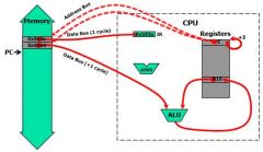
H to show hint;
A reads text to speech;
49 Cards in this Set
- Front
- Back
|
5 8000 540A RESET: add.w r4,r10 |
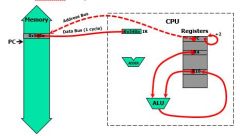
Register |
|
|
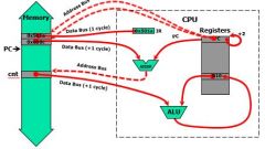
6 8002 541A add.w 6(r4),r10 |
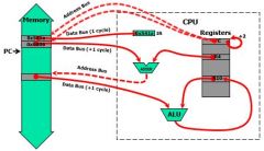
Indexed Register |
|
|
7 8006 542A add.w @r4,r10
|
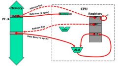
Indirect Register |
|
|
8 8008 543A add.w @r4+,r10 |
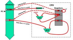
Indirect Auto-inc |
|
|
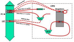
9 800a 501A add.w cnt,r10 |
Symbolic or PC |
|
|
10 800e 521A add.w &cnt,r10 |
Absoulute |
|
|
11 8012 503A add.w #100,r10 |
Immediate r10 = 100 + r10 |
|
|
12 8016 531A add.w #1,r10 |
Constant r10 = 1 + r10 |
|
|
13 8018 5090 add.w cnt,var |
3 Word Instruction(6 cycles) |
|
|
1. There are two basic models of computing machines. What are they?
a) RISC, CPU b) CISC, CPU c) RISC, CISC d) RISC, RAM |
c) RISC, CISC |
|
|
2. Assembly language instructions are translated to machine language instructions by _________. a) Compiler b) Debugger c) Loader d) Assembler |
d) Assembler |
|
|
3. _____________ defines all of the programmer visible components and operations of computer. a) Register Set b) Memory Organization c) Programming Languages d) Instruction Set Architecture |
d) Instruction Set Architecture |
|
|
4. MSP430 has ________ basic (i.e., native) instructions and __________ addressing modes. a) 27, 7 b) 50, 27 c) 7, 27 d) 27, 50 |
a) 27, 7 |
|
|
5. This special register in MSP430 has the address of the next instruction to be fetched by CPU. a) Status Register b) Stack Pointer c) Program Counter d) Constant Generator |
c) Program Counter |
|
|
6. The MSP430 CPU pushes the return address of subroutine calls and interrupts on the ________. a) Register Set b) Stack c) Status Register d) Program Counter |
b) Stack |
|
|
7. The number of bits in MSP 430 (i.e., one word) is ___________. a) 8 bit b) 16 bits c) 32 bits d) 64 bits |
b) 16 bits |
|
|
8. In MSP 430, the status bits such as V, N, Z, and C are automatically updated after ALU performs the arithmetic and/or logic operations. a) True b) False |
a) True |
|
|
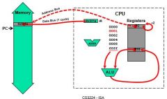
9. During the __________ cycle, CPU in MSP430 finds the next instruction from the memory pointed by PC and loads the instruction into Instruction Register. a) Decode b) Execution c) Fetch d) Write Back |
c) Fetch |
|
|
10. In MSP 430, there are three types of instructions. Which instruction type below does not belong to MSP430 instruction types? a) Type 1 (Instructions with two operands) b) Type 2 (Instruction with one operand) c) Add/Load Instruction Type d) Jump Instruction |
c) Add/Load Instruction Type |
|
|
11. Which of the following MSP430 instructions can be used to set bits in destination? a) BIC b) BIS c) BIT d) MOV |
b) BIS |
|
|
12. Suppose we have the following machine instruction “0100 0101 0000 0100”. What is the corresponding MSP 430 assembly language instruction? a) mov.w R5, R4 b) add.w R4, R5 c) mov.b R4, R5 d) add.b R5, R4 |
a) mov.w R5, R4
|
|
|
13. Suppose we have the following assembly instruction “rrc.w R5”. What will be the machine code for this assembly instruction? a) 0001 0000 0000 0101 b) 0001 0001 1000 0101 c) 1110 0000 0000 0101 d) 1110 0001 1000 0101 |
a) 0001 0000 0000 0101 |
|
|
14. Which of the following assembly instruction can provide an infinite loop? a) jmp loop b) jc loop c) jmp $ d) jc $ |
c) jmp $ |
|
|
15. How many different addressing modes are defined in MSP430? a) 4 b) 5 c) 6 d) 7 e) None of the above |
d) 7
|
|
|
16. Consider the following instruction. Where are the first operand the second operand located? Add.w @R4, R10 a) Register, Memory b) Memory, Register c) Memory, Memory d) Register, Register |
b) Memory, Register
|
|
|
17. Consider the following instruction. How many cycles will be required for CPU to process this instruction? (Consider the data bus only when the CPU cycles are calculated.) Add.w @R4, R10 a) 1 b) 2 c) 3 d) 4 |
b) 2
|
|
|
18. Which assembly language instruction below will require the most CPU cycles? (Consider the data bus only.) a) add.w cnt, var b) add.w &cnt, r10 c) add.w @R4, R10 d) add.w R4, R10 |
a) add.w cnt, var
|
|
|
19. In the 2’s complement signed number system, what will be the binary value of “decimal -6”? a) 1010 b) 0110 c) 1011 d) 0111 |
a) 1010
|
|
|
20. In the 2’s complement signed number system with n = 4 bits, what will be the minimum and the maximum numbers that can be represented? a) -7, +7 b) -8, +7 c) -7, +8 d) -8, +8 |
b) -8, +7
|
|
|
21. In a 4-bit signed number system (e.g., 2’s complement number system), select the one that would cause an overflow from the list below. a) 5 + 4 b) 4 + 2 c) -5 – 4 d) -4 -2 |
a) 5 + 4
|
|
|
Describe the MSP430 ISA
-Instructions(type and number) -Addressing Modes(number) |
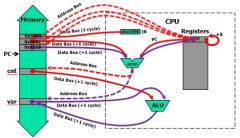
RISC/CISC machine -27 orthogonal instructions 8 jump instructions 7 single operand instructions 12 double operand instructions -7 addressing modes. -8/16-bit instruction addressing formats. Memory architecture -16 16-bit registers -16-bit Arithmetic Logic Unit (ALU). -16-bit address bus (64K address space) -16-bit data bus (8-bit addressability) -8/16-bit peripherals |
|
|
Levels of Transformation |
slide 19 |
|
|
MSP430 Registers How many? What do they do? |
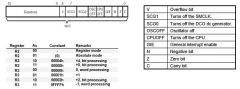
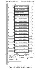
R0 (PC) – Program Counter -Points to (has the address of) the next instruction to be fetched. -Each instruction occupies an even number of bytes. Therefore, the least significant bit (LSB) of the PC register is always zero. -After executing an instruction, the PC register will have incremented by 2, 4, or 6 and point to the next instruction. R1 (SP) – Stack Pointer -The MSP430 CPU pushes the return address of subroutine calls and interrupts on the stack. -User programs store local data on the stack. -The SP can be incremented or decremented automatically with each stack access. -The stack “grows down” thru RAM and thus SP must be initialized with a valid RAM address. -SP always points to an even address, so its LSB is always zero. R2 (SR/CG1) – Status Register -The status of the MSP430 CPU is found in register R2. -Only accessible through register addressing mode - all other addressing modes are reserved to support the constant generator. R3 (CG2) – Constant Generator slide23 |
|
|
MSP430 ALU - 16 bit Arithmetic Logic Unit (ALU). -Functions -Flags |
-Performs instruction arithmetic and logical operations. -Instruction execution affects the state of the following flags: Zero (Z) Carry (C) Overflow (V) Negative (N) -The MCLK (Master) clock signal drives the CPU and ALU logic. slide 24 |
|
|
MSP430 Memory Organization |
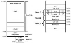
A little-endian machine stores the least significant byte first (lowest address) within a word data type. slide 25 |
|
|
I/O Ports (*) What are the Registers? |
Direction Register (PxDIR): Bit = 1: the individual port pin is set as an output Bit = 0: the individual port pin is set as an input Input Register (PxIN): When pins are configured as GPIO, each bit of these read-only registers reflects the input signal at the corresponding I/O pin Bit = 1: The input is high Bit = 0: The input is low Output Register (PxOUT): Each bit of these registers reflects the value written to the corresponding output pin. Bit = 1: The output is high; Bit = 0: The output is low. Note: the PxOUT is a read-write register which means previously written values can be read, modified, and written back |
|
|
MSP430 Assembler What are the parts? |
1. label—starts in the column 1 and may be followed by a colon (:) for clarity. case sensitive, but instructions and directives are not - pick a style and stick with it. 2. operation—either an instruction, which is translated into binary machine code for the processor itself, or a directive, which controls the assembler. 3. operands—data needed for this operation (not always required). 4. comment—text following a semicolon (;). |
|
|
MSP430 Instruction Formats
|

Format I: Instructions with two operands: Format II: Instruction with one operand: Format III: Jump instructions: slide 37 |
|
|
Double Operand (*) Copy the contents of a register to another register Assembly: mov.w r5,r4 Instruction code: 0x4504 How many words? What happens with registers? |
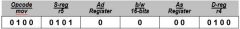
-One word instruction -The instruction instructs the CPU to copy the 16-bit 2’s complement number in register r5 to register r4 s39 |
|
|
Single Operand Logically shift the contents of register r5 to the right through the status register carry Assembly: rrc.w r5 Instruction code: 0x1005 How many words? What happens with registers? |
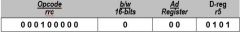
-One word instruction -The CPU shifts the 16-bit register r5 one bit to the right (divide by 2) – the carry bit prior to the instruction becomes the MSB of the result while the LSB shifted out replaces the carry bit in the status register s43 |
|
|
Jump Instruction Format How are they used? Under what conditions? |
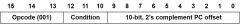
Jump instructions are used to direct program flow to another part of the program. The condition on which a jump occurs depends on the Condition field consisting of 3 bits: -000: jump if not equal -001: jump if equal -010: jump if carry flag equal to zero -011: jump if carry flag equal to one -100: jump if negative (N = 1) -101: jump if greater than or equal (N = V) -110: jump if lower (N V) -111: unconditional jump s44 |
|
|
Jump Instruction Format |
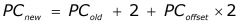
-Jump instructions are executed based on the current PC and the status register -Conditional jumps are controlled by the status bits -Status bits are not changed by a jump instruction -The jump off-set is represented by the 10-bit, 2’s complement value: -Thus, the range of the jump is -511 to +512 words, (-1023 to 1024 bytes ) from the current instruction -Note: Use a BR instruction to jump to any address s45 |
|
|
Jump Format Continue execution at the label main if the carry bit is set -Assembly: jc main -Instruction code: 0x2fe4 |
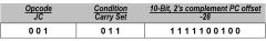
-One word instruction -The CPU will add to the incremented PC (R0) the value -28 x 2 if the carry is set s46 |
|
|
Unconditional Jump(*) |
-Unconditional (conditional) jump fits in one single word, including 10-bit offset -So it limits to jump about +/- 1KB from current location -Normally use jump within a routine (This is opposite to MIP2000 jump). ex. jmp $ ; jump to the current location, infinite loop |
|
|
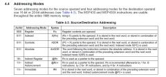
Source Addressing Modes How many? What are they? |
The MSP430 has four modes for the source address: -00 = Rs - Register -01 = x(Rs) - Indexed Register -10 = @Rs - Register Indirect -11 = @Rs+ - Indirect Auto-increment In combination with registers R0-R3, three additional source addressing modes are available: -label - PC Relative, x(PC) -&label – Absolute, x(SR) -#n – Immediate, @PC+ Key: s and x are numbers |
|
|
Destination Addressing Modes How many? What are they? |
There are two modes for the destination address: -0 = Rd - Register -1 = x(Rd) - Indexed Register In combination with registers R0/R2, two additional destination addressing modes are available: -label - PC Relative, x(PC) -&label – Absolute, x(SR) key: label= count, var... |
|
|
How Many addressing modes are there? How are they represented in assembly and machine language? |
s61 |
|
|
How to Find # of Cycles Per Instruction... |
1 cycle to fetch instruction word - +1 cycle if source is @Rn, @Rn+, or #Imm - +2 cycles if source uses indexed mode --1st to fetch base address --2nd to fetch source --Includes absolute and symbolic modes - +2 cycles if destination uses indexed mode - +1 cycle if writing destination back to memory - +1 cycle if writing to PC (R0) - Jump instructions are always 2 cycles |
|
|
How to find length of instructions(in words) |
*Not really sure* It seems to be (# of cycles)/2, round down. Nothing less than 1 write chart in cheat sheet |