![]()
![]()
![]()
Use LEFT and RIGHT arrow keys to navigate between flashcards;
Use UP and DOWN arrow keys to flip the card;
H to show hint;
A reads text to speech;
38 Cards in this Set
- Front
- Back
|
Consists of logic gates whose outputs at any time are determined directly from the present combination of inputs without regard to previous inputs. |
Combinational Circuits |
|
|
Adds mathematically 2 bits |
Half adder |
|
|
Adds mathematically 3 bits |
Full Adder |
|
|
Subtracts 2 bits |
Half Subtracter |
|
|
Subtracts 3 bits |
Full Subtracter |
|
|
Produces the arithmetic sum of 2 binary numbers in parallel |
Binary Parallel Adder |
|
|
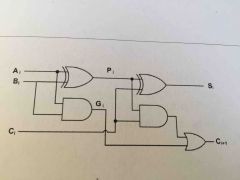
Look Ahead Carry Generator Circuit |
|
|
|
Produces an output carry when both Ai and Bi are one |
Carry generate (Gi) |
|
|
Associated with the propagation of the carry from Ci to C(i+1) |
Carry Propagate (Pi) |
|
|
Addition of 2 decimal digits in BCD with carry from a previous state |
BCD Adder |
|
|
Combinational circuit that compares two numbers, A and B, and determines their relative magnitude. |
Magnitude Comparator |
|
|
Converts binary information from n input lines to a maximum of 2^n unique output lines |
Decoder |
|
|
Any Boolean function can be expressed in __ |
Sum of Minterms |
|
|
Use a decoder to generate the __ and an external __ to form the sum |
Minterms - OR gate |
|
|
Has 2^n input lines and n output lines |
Encoder |
|
|
Combinational circuit that selects binary information from one of many input lines and directs it to a single ouput line |
Multiplexer |
|
|
A circuit that receives information in a single line and transmits this information to one of 2^n possible output lines. |
Demultiplexer |
|
|
Consists of a combinational circuit to which memory elements are connected to form a feedback path |
Sequential Circuit |
|
|
A device with 2 stable states |
Flip Flops |
|
|
- A device with 2 stable states - It can maintain a binary state indefinitely until directed by an input signal to switch states - It remains in one of these states until triggered into the other. |
Flip Flops |
|
|
Transistor Latch Diagram |
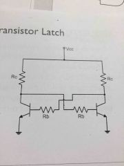
Back (Definition) |
|
|
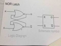
RS Flip flop (NOR Latch) |
|
|
|
2 Types of Clocking/Triggering |
Level Clocking Edge Triggering |
|
|
Output for the flip flop responds during the high (or low) level of the clock signal |
Level Clocking |
|
|
The flip flop produces output only on the rising (or falling) edge of the clock signal |
Edge Triggering |
|
|
Two external inputs that initiates the condition or state of the flip flop. |
Preset and Clear |
|
|
This represents the amount of time it takes for the output of a gate or flip flop to change states |
Propagation Delay Time (tp) |
|
|
It is the minimum length of time the data bit must be present before the clock edge hits |
Setup Time (tsetup) |
|
|
It is the minimum length of time the data bit must be present after the clock edge has struck. |
Hold Time (thold) |
|
|
Graphical representation of the truth table |
Karnaugh Map (K-Map) |
|
|
Graphical representation of the truth table |
Karnaugh Map (K-Map) |
|
|
A set of exactly 2^m adjacent cells containing ones or zeroes |
Subcubes |
|
|
Identical except in one variable |
Adjacent |
|
|
Does not affect the system Could be 1 or 0 |
Don't Cares |
|
|
Other name for Tabulation Method |
Quine-McCluskey Method |
|
|
Specific step by step procedure that is guaranteed to produce a simplified standard form expression for a function |
Tabulation Method |
|
|
Those not checked in the table |
Prime Implicants |
|
|
Prime implicants that cover minterms with a single check in their column |
Essential Prime Implicants |