![]()
![]()
![]()
Use LEFT and RIGHT arrow keys to navigate between flashcards;
Use UP and DOWN arrow keys to flip the card;
H to show hint;
A reads text to speech;
134 Cards in this Set
- Front
- Back
|
What are the "Primary" flight controls? |
Rudder
Elevator Ailerons |
|
|
What are the "Secondary" flight controls?
|
Flaps |
|
|
Where are the "Powered Flight Control Surfaces" (PFCS) control positions displayed?
|
On the lower section of the captain's MFD. |
|
|
Control positions for the Powered Flight Control Surfaces are transmitted to the captain's MFD through what? |
Integrated Flight Cabinet (IFC)
|
|
|
The spoilers have three (3) modes of operation. What are they?
|
Flight Mode
Ground Mode Taxi Mode |
|
|
What do the spoilers provide for while in the "Flight Mode"?
|
Roll assist to the ailerons.
|
|
|
What do the spoilers provide for while in the "Ground Mode"?
|
Lift Dumping
|
|
|
What is the purpose of the "Flight Control Electronic Control Unit" (FCECU)?
|
Receives and sends electrical inputs for the primary flight control systems.
|
|
|
Where is the Flight Control Electronic Control Unit (FCECU) physically located on the aircraft?
|
Under the passenger cabin floor.
|
|
|
The Flight Control Electronic Control Unit (FCECU) has two channels. What is the power source for each channel?
|
Left Channel: Left Essential DC Bus
Right Channel: Right Essential DC Bus |
|
|
What does the Flight Control Electronic Control Unit (FCECU) send electronic outputs to?
|
1. Primary Flight Controls
2. Secondary Flight Controls 3. Flight Data Recorder 4. Advisory Systems 5. Caution Indicating Systems |
|
|
How are the "elevators" controlled?
|
Mechanically controlled / Hydraulically actuated
|
|
|
Which elevator surface does the captain's yoke control?
|
Left elevator
|
|
|
Which elevator surface does the first officer's yoke control?
|
Right elevator
|
|
|
How are the elevator surfaces connected together?
|
By a "Pitch Disconnect System". |
|
|
What is the purpose of the "Pitch Disconnect System" for the elevators?
|
Allows you to disconnect the two elevator halves in the event of a control jam (PCU Failure).
|
|
|
Where is the elevator position information displayed?
|
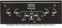
On the "Powered Flight Control Surface" indicator on MFD #1. |
|
|
How many PCU's are there for each elevator half?
|
Three (3)
|
|
|
What are the names of the PCU's on each elevator half?
|
Inboard PCU
Center PCU Outboard PCU |
|
|
Are all the PCUs active at all times for the elevator?
|
No
Only the Outboard and Center PCU's are normally active. The Inboard PCUs act as a "Standby Unit". |
|
|
What source powers the elevator PCU's?
|
Inboard PCUs: Hydraulic System #3
Center PCUs: Hydraulic System #2 Outboard PCUs: Hydraulic System #1 |
|
|
What prevents a PCU runaway in the elevator system?
|
Input Bungees
|
|
|
What is the purpose of the "PCU Compensator" in the elevator system?
|
1. Maintains "positive pressure" on the elevator system for gust lock protection while on the ground.
2. Provides "flutter suppression" while inflight with a loss of hydraulics. Note: The PCU Compensator is installed in the "return line" of Hydraulic System #3. |
|
|
What provides "artificial feel" for the elevator system?
|
Two (2) "Pitch Feel and Trim Units" (PFTU's).
|
|
|
Where are the Pitch Feel and Trim Units installed on the aircraft for the elevator system?
|
On the upper section on each side of the vertical stabilizer just below the elevator halves.
|
|
|
What does each Pitch Feel and Trim Unit control?
|
Left PFTU: Left Elevator
Right PFTU: Right Elevator |
|
|
Inputs from the Pitch Feel and Trim Units is automatically applied to the elevators to control artificial feel dependent on what?
|
1. Airspeed
2. Acceleration |
|
|
Elevator trim is controlled by what two (2) methods?
|
1. Manually by using the trim switches on each yoke.
2. Automatically by the autopilot when engaged. |
|
|
Elevator pitch trim "rate" is automatically controlled by the FCECU dependent on what?
|
Aircraft's airspeed. |
|
|
Where is the elevator trim position displayed?
|
On the Elevator Trim Indicator located on the left side of the center console next to the Parking Brake handle. |
|
|
What will occur if the elevator trim remains in motion for too long a period?
|
If the elevator trim remains in motion for over 3 seconds the following will occur: |
|
|
At what time will the "Flap Auto Pitch Trim" system function?
|
1. The autopilot is not engaged. |
|
|
What is the "priority" of the pitch trim system?
|
1. Captain's Trim
2. First Officer's Trim 3. Autopilot Trim 4. Flap Auto Trim |
|
|
At what times is the "Flap Auto Pitch Trim System" deactivated?
|
1. On Ground (WOW).
2. Airspeed is greater than 200 kts. 3. The autopilot is engaged. 4. Flaps are not moving between 15 and 35 degrees. 5. Manual Pitch Trim is commanded. 6. Pitch commands are in excess of pitch limits. 7. Flight control or AFCS system failure. |
|
|
What will occur if either Hydraulic System #1 "or" Hydraulic System #2 pressure is lost to the elevator system?
|
Hydraulic System #3 pressure will automatically "activate" and provide pressure to the Inboard PCU's.
The "HYD #3 ISOL VALVE" switchlight "will not" illuminate unless manually pressed. |
|
|
In the event of Hyd Sys #1 or Hyd Sys #2 failure "AND" Hyd Sys #3 "does not automatically activate", how can Hyd Sys #3 pressure be "manually" activated?
|
By pressing the "HYD #3 ISOL VALVE" switchlight.
|
|
|
How can it be confirmed that Hydraulic System #3 pressure has "automatically activated" for the elevator system?
|
By an indication of Hydraulic System #3 pressure on MFD #2.
|
|
|
What will occur if an elevator position mis-match occurs?
|
The "ELEVATOR ASYMMETRY" caution light will illuminate.
NOTE: Do not exceed 200 kts with the caution illuminated! |
|
|
What will occur in the event that the FCECU is unable to command the Pitch Feel Actuator?
|
1. "ELEVATOR FEEL" caution will illuminate.
2. The failed actuator is held in its last valid position. 3. Pitch feel will be de-graded. NOTE: Do not exceed 200 kts! The remaining actuators will operate normally. |
|
|
What will be displayed if the two (2) Pitch Trim Actuators are in disagreement?
|
The "PITCH TRIM" caution will be displayed.
|
|
|
What is indicated by the "ELEVATOR PRESS" caution light?
|
It indicates that "all three (3) hydraulic systems" are providing pressure to the elevator system.
This would be an indication that the "#3 HYD Isolate Valve" has failed "OPEN". |
|
|
What connects the captain's and first officer's rudder pedals together?
|
An "Interconnect Rod".
|
|
|
What provides artificial feel to the rudder system?
|
A "Feel Spring Unit".
|
|
|
The rudder consists of two (2) sections. What are they called?
|
Fore Section
Aft Section |
|
|
How many PCU's are there for the "Fore Section" of the rudder?
|
Two (2)
|
|
|
What supplies power to the two (2) PCUs for the rudder?
|
Upper PCU: Hydraulic System #2
Lower PCU: Hydraulic System #1 |
|
|
How is the "AFT section" of the rudder deflected?
|
Mechanically via pushrods.
It will deflect "Twice as far" as the fore section. |
|
|
What is the purpose of the rudders "Input Restrictor"?
|
It will limit rudder travel depending on flap position.
- Flaps "at 0 degree (UP) detent": +/- 12 degrees - Flaps "out of 0 degree detent": +/- 18 degrees |
|
|
What is the "Rudder Input Restrictor" linked to?
|
The first officer's rudder pedals.
|
|
|
How is hydraulic pressure regulated to the rudder PCU's?
|
The FCECU will automatically regulate pressure to the rudders dependent on airspeed.
With an "increase" in speed less pressure is allowed to the rudder. |
|
|
How is "artificial feel" provided for on the rudder system?
|
By a "Rudder Feel Trim and Summing Unit".
|
|
|
Where is the rudder trim control knob located?
|

On the center console. |
|
|
How many speeds can the rudder trim operate at?
|

Two (2) |
|
|
What will the rudder trim indicator show if the indicator has failed?
|
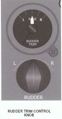
Off Scale. |
|
|
How does the "Yaw Damper" system operate?
|
It provides electronic inputs to the rudder "Summing Unit". |
|
|
What is the deflection "authority" of the Yaw Damper System?
|
+/- 4.5 degrees deflection |
|
|
What two (2) ways may the Yaw Damper system be selected to "ON"?
|
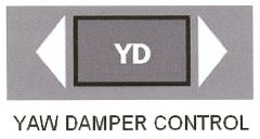
1. Manually by selecting the Yaw Damper switchlight. |
|
|
What is required for the Yaw Damper system to function?
|
Inputs from "BOTH" Flight Guidance Module 1 (FGM1) and Flight Guidance Module 2 (FGM2).
|
|
|
What will be displayed if a jam occurs in the "lower" rudder PCU? |
"RUD 1" switchlight on the glareshield will illuminate. |
|
|
What will be displayed if a jam occurs in the "Upper" rudder PCU?
|
"RUD 2" switchlight on the glareshield will illuminate. |
|
|
If the "RUD 1" or "RUD 2" switchlights on the glareshield illuminate is hydraulic pressure automatically removed from the respective PCU?
|

No |
|
|
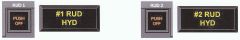
If the "RUD 1" or "RUD 2" switchlight on the glareshield is pressed, what other caution light will be illuminated?
|
The respective "#1 RUD HYD" or "#2 RUD HYD" caution light will illuminate.
|
|
|
At what time will the "RUD CTRL" caution light illuminate?
|
When the FCECU is unable to control pressure to the rudder PCU's due to:
1. Failure of "both" FCECU channels. 2. Loss of Hydraulic System #1 "and" Hydraulic System #2. 3. A significant disagreement in airspeed signals occurs. NOTE: Limit the aircraft's speed to 200 kts! |
|
|
At what time does the respective "#1/#2 RUD HYD" caution light illuminate?
|
Loss of hydraulic system pressure to the respective rudders PCU.
|
|
|
Do the ailerons have any hydraulic control?
|
No
They are mechanically operated "and" controlled. |
|
|
Do the spoilers have any hydraulic control?
|
Yes
The spoilers are mechanically controlled but hydraulically actuated. |
|
|
Are the spoilers and ailerons all part of the same system?
|
No
They are independent systems. |
|
|
Which yoke controls the Flight Spoilers?
|
The Captain's yoke.
|
|
|
Which yoke controls the ailerons?
|
The first officer's yoke.
|
|
|
Are the spoiler and aileron systems connected together?
|
Yes
They are mechanically connected together and separated using the "Roll Disconnect". |
|
|
At what time would the "Roll Disconnect" be pulled for the aileron and spoiler systems?
|
When a control jam occurs in either the ailerons or spoilers systems.
|
|
|
How many aileron and spoiler panels are there on each wing?
|
One (1) Aileron panel
Two (2) Spoiler panels |
|
|
What is the purpose of the "Geared Tab" on each aileron?
|
It provides aerodynamic assistance.
The tab will move "opposite" the aileron deflection. |
|
|
Where is the "Ground Adjustable Trim Tab" located on the aileron system?
|
Only on the "right aileron".
|
|
|
What is the purpose of the "Aileron Trim and Centering Unit" (ATCU)?
|
It provides automatic centering of the ailerons back to neutral when control pressures are released.
|
|
|
What does the "Control Lock" on the power quadrant do?
|
1. Prevents forward movement of the Power Levers.
2. It will lock the ailerons in the "neutral position". NOTE: Do not attempt to trim the ailerons with the control lock engaged or damage could occur to the aileron system! |
|
|
What must be accomplished if a "MISTRIM [TRIM L WING DWN]" message occurs with the autopilot engaged?
|
You must disengage the autopilot and manually remove the trim pressures prior to re-engaging the autopilot.
|
|
|
What will occur if an "aileron trim runaway" occurs?
|
1. The "Travel Limit Switch" will automatically shutoff hydraulic power to the trim actuator.
2. If the Travel Limit Switch "fails" to remove hydraulic power then a mechanical stop will limit the actuator to the "maximum trim setting". |
|
|
How many spoiler panels are there on each wing?
|
Two (2)
Inboard and Outboard |
|
|
How are the spoiler panels extended and retracted?
|
Hydraulically through the PCU's.
|
|
|
Where is the Roll Spoilers position indicated?
|

At the bottom of MFD #1 |
|
|
When in the "Flight Mode" how much are the spoilers extended?
|
In proportion to the "UP" aileron. (Down Wing)
|
|
|
Which hydraulic systems powers the spoilers?
Inboard Spoilers: Outboard Spoilers: |
Inboard Spoilers: Hydraulic System #1
Outboard Spoilers: Hydraulic System #2 Remember: The inboard spoilers are always active so they are the #1 system! |
|
|
Are both the Inboard and Outboard spoilers active at all times while in the "Flight Mode"?
|
No
The outboard spoilers are deactivated when the airspeed is "above" 170 kts. Extension pressure is "shutoff" via the FCECU. |
|
|
When operating in the "Ground Mode" how many Lift Dumper Valves are there to control the spoilers extension?
|
Four (4)
- One for each spoiler panel. |
|
|
In order for the "Ground Spoilers" to extend, what must occur?
|
1. The "FLIGHT/TAXI" switch must be in the FLIGHT (UP) position.
"AND" 2. Both power levers must be "at or behind" the Flight Idle gate. "AND" 3. Weight on Wheels must be detected on "BOTH" main gear. |
|
|
Following landing how is ground spoiler extension verified?
|
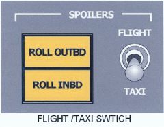
By the two (2) "Ground Extension" advisory lights next to the FLIGHT/TAXI switch. |
|
|
What is the purpose of moving the "FLIGHT/TAXI" switch to the TAXI position following landing?
|
It takes the spoilers out of the ground mode and retracts all the spoiler panels for taxi.
|
|
|
What will occur if the "FLIGHT/TAXI" switch is not selected to the FLIGHT position prior to takeoff?
|
The switch is spring loaded and will automatically flip up to the FLIGHT position.
The "Hold-In Solenoid" is magnetically released which held the switch to the TAXI mode. |
|
|
What will protect the spoilers in the event of a jammed PCU?
|
The "Spoiler Clutch" will automatically dis-engage the jammed spoiler panel and illuminate the appropriate "SPLR1" or "SPLR2" switchlight. |
|
|
If the "SPLR1" or "SPLR2" switchlight on the glaresheild illuminates following a jammed spoiler PCU, is the hydraulic pressure automatically removed from the affected PCU?
|
No |
|
|
If the "SPLR1" or "SPLR2" switchlight is pressed on the glareshield, what other caution will illuminate?
|
If the "SPLR1" switchlight is pressed:
- "ROLL SPLR INBD HYD"
If the "SPLR2" switchlight is pressed:
- "ROLL SPLR OUTBD HYD" |
|
|
What is indicated if the aileron control wheel will not move?
|
Either an aileron cable malfunction "or" a spoiler PCU has failed. |
|
|
What caution will illuminate if there is a loss of hydraulic pressure to the spoiler panels PCU?
|
The associated "ROLL SPLR INBD HYD" or "ROLL SPLR OUTBD HYD" caution light.
|
|
|
If the "Outboard Spoiler" panels do not automatically de-activate above 170 kts what caution light will illuminate?
|
"SPLR OUTBD" caution light
|
|
|
If a "Lift Dump Valve" fails to open and extend a ground spoiler panel, how is it indicated?
|
You will receive the associated "ROLL SPLR INBD GND" or "ROLL SPLR OUTBD GND" caution light.
|
|
|
What will occur if the takeoff roll is initiated and the spoilers "remain extended"?
|
1. Takeoff Warning tone is heard. |
|
|
How many flap panels are there on each wing?
|
Two (2)
|
|
|
What sends the signal to move the flaps?
|
The "Flap Control Unit" (FCU) electrically sends the signal to the "Flap Power Unit" (FPU) to move the flaps.
|
|
|
Which hydraulic system powers the Flap Power Unit (FPU)?
|
Hydraulic System #1
|
|
|
Does the Flap Power Unit (FPU) hydraulically move the flap actuators?
|
No
It converts hydraulic power into "rotary motion" to operate the flap actuators. |
|
|
How many detents are there on the Flap Selector Lever?
|
Five (5)
0, 5, 10, 15 and 35 degrees |
|
|
What must be accomplished to allow the flap selector lever to be moved?
|
A trigger mechanism beneath the flap lever must be depressed.
|
|
|
What two (2) functions does the "Flap Position Indicator Unit" (FPIU) accomplish?
|
1. Monitors the flap position during extension and retraction and sends data to the FCU.
2. Supplies the current flap position data to MFD #2. |
|
|
At what time will the "Flap Control Unit" automatically activate the "Standby Hydraulic Pump" and the "Power Takeoff Unit (PTU)"?
|
1. When the flaps are selected "out of the 0 degree detent".
"AND" 2. The Parking Brake is released. |
|
|
Does the Flap Selector Lever mechanically or electrically send the signal to the Flap Control Unit?
|
Electrically
|
|
|
At what time will the Flap Control Unit command the flaps to move?
|
When the flap selector lever has reached the first hard gate.
|
|
|
What "enables" the Flap Control Unit?
|
Pressing the trigger underneath the flap selector will "arm" the FCU.
|
|
|
How many actuators are there for the flap system?
|
Eight (8)
Two (2) on each flap panel. |
|
|
What are the two (2) caution lights associated with flap extension and retraction?
|
"FLAP POWER"
"FLAP DRIVE" |
|
|
What automatically occurs if the "FLAP POWER" caution light illuminates?
|
The Flap Control Unit will "inhibit" further flap movement and lock the flaps in the last position reached prior to failure.
|
|
|
What will automatically occur if the "FLAP DRIVE" caution light illuminates?
|
The flaps may still operate but with reduced performance.
If the failed condition goes away the system will automatically reset itself. |
|
|
What are the two (2) primary functions of the "Stall Protection System (SPS)?
|
Stick Shaker Operation
Stick Pusher Operation |
|
|
What do the two (2) "Stall Protection Modules" (SPM's) do?
|
They control both Stick Shaker and Stick Pusher activation.
|
|
|
What parameters do the "Stall Protection Modules (SPM's) monitor for "Stick Shaker" activation?
|
1. Angle of Attack
2. Flap Position 3. Mach Number 4. Engine Torque 5. Icing Status (input from the "REF SPEEDS" switch) |
|
|
What parameters do the "Stall Protection Modules" (SPM's) monitor for "Stick Pusher" activation?
|
1. Angle of Attack
2. Flap Position 3. Mach Number 4. Power Lever Angle 5. Condition Lever Angle 6. Icing Status (input from the "REF SPEEDS" switch) |
|
|
The stall protection system will only operate when the following conditions are met:
|
1. True/Calibrated airspeed is below 215 kts.
2. Altitude is above 500 feet AGL. 3. The stick pusher switch "is not selected to OFF". |
|
|
What is the purpose of the "Angle of Attack" (AOA) transducers?
|
They provide angle of attack information to the Stall Protection System.
|
|
|
Where is AOA1 physically located on the aircraft?
|
Left side of nose.
|
|
|
Where is AOA2 physically located on the aircraft?
|
On the right side of the nose.
|
|
|
Are the AOA vanes heated?
|
Yes
They have "self regulated" heaters which are active anytime that AC power is available to the aircraft. |
|
|
What will occur if one of the AOA transducers heater fails?
|
The Stall Protection Modules will not use that AOA vanes input data!
|
|
|
Where is the Stick Pusher physically located on the aircraft?
|
It is installed on the Captain's yoke only!
|
|
|
In order for the stick pusher to function what must be operational?
|
1. Both "Stall Protection Modules" must be operational.
2. The "STICK PUSHER SHUTOFF" switches must not be turned "OFF". |
|
|
How can the Stick Pusher system be deactivated?
|

By pressing the "STICK PUSHER SHUTOFF" switchlights on either side of the the glareshield. |
|
|
If the "STICK PUSHER SHUTOFF" switchlight is pressed on the glareshield what caution lights will illuminate?
|
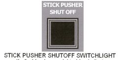
1. "PUSHER SYST FAIL" caution light |
|
|
At what time is the Stick Pusher System rendered inoperative?
|
1. When either AOA transducer fails.
"or" 2. A substantial difference between the two transducer positions occurs. |
|
|
Once "activated" how long will the Stick Pusher operate?
|
It will operate for only 15 seconds and then it goes through a 1 minute wait period prior to activating again.
|
|
|
Is it possible for the pilot's to overcome the stick pusher by applying force to the control column?
|
Yes
Approximately 80 pounds of force will over power the stick pusher. |
|
|
What changes will occur with the Stall Protection System (SPS) while operating in icing conditions?
|
The activation angle is set "slightly lower".
This is automatically selected when the "REF SPEEDS" switch on the Ice Protection Panel is selected to the "INCR" position. |
|
|
When the "REF SPEEDS" switch is selected to the "INCR" position on the Ice Protection Panel what annunciation will be displayed?
|
An "INCR REF SPEED" message will appear on the bottom of the Engine Display Panel.
|
|
|
What is actually being tested when the spring-loaded switch for the Stall Protection system is selected to the following positions?
"TEST 1" / "TEST 2" |
"TEST 1":
Tests Stall Protection Module #1 (SPM1) "TEST 2": Tests Stall Protection Module #2 (SPM2) |
|
|
When conducting the Stall Protection System "Test", how is a satisfactory test indicated?
|
1. Activation of the Left and Right Stick Shakers.
2. Illumination of the respective "#1/#2 STALL SYST FAIL" and "PUSHER SYST FAIL" caution lights. 3. The stick pusher will stop and all caution lights will extinguish. |
|
|
Will failures of the Stall Protection System be indicated while "inflight"?
|
Non-critical malfunctions will not be indicated until 30 seconds after landing.
Failures which would render the Stick Shaker or Stick Pusher inoperative will be indicated while in-flight! |