Reading...
![]()
Play button
![]()
Play button
![]()
Use LEFT and RIGHT arrow keys to navigate between flashcards;
Use UP and DOWN arrow keys to flip the card;
H to show hint;
A reads text to speech;
50 Cards in this Set
- Front
- Back
|
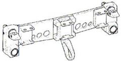
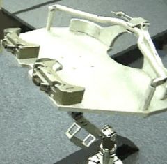
Modular Baseplate Assembly
- standard ball lock type latching system to attach to the EMU - serves as mounting point for any of the following MMWS system components: -- swing arm assembly, -- right/left hand swing arm assembly, -- retracting end effector assembly; -- and the modular gimbal assembly - modular baseplate also includes a mounting base for the Body Restraint Tether (BRT) or the Multi-Use Tether (MUT). |
|
|
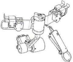
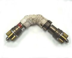
Modular Gimbal Assembly
- consists of the T-bar assembly and the push button gimbal assembly. -- gimbal design consists of one push button that engages/ disengages a spline system that allows for gimbal rotation and latching. The gimbal design allows the T-bar assembly to be pivoted away from the EMU up to 135 degrees through 9 detent positions (detent secures the T-bar in the desired position). The gimbal design also contains a load alleviating clutch system which will slip to prevent overloading the EMU attachment fittings. -- T-bar assembly contains a crossbar, retractable end effector assembly and four bayonet receptacles. Each bayonet receptacle is used to retain equipment, and each receptacle has a slide lock to secure the equipment in the receptacle. |
|
|
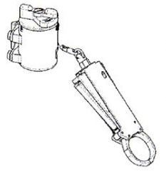
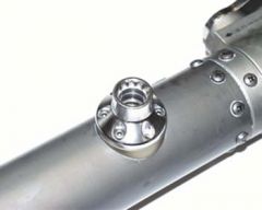
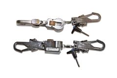
Retracting End Effector Assembly
- consists of a dual lever end effector assembly and a retracting tether assembly. - contains 45 inches of cord and a lock-out mechanism that prevents the cord from retracting or deploying at any length. - end effector allows an EVA crewmember to attach and position him/herself at the worksite, lock the end effector [to prevent inadvertent release], and then fix the desired length of the retractable cord freeing the crewmember for any necessary two handed operations. - end effector has the capability to lock onto a handrail, tether point, or tether loops. Note: Crew have reported sticky end effectors during space walks due to the thermal cycles the tool experiences. Operational Work Around: The BRT (or alternate tethers) may be used for body stabilization in lieu of the MMWS EE. |
|
|
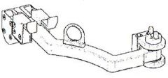
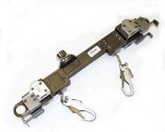
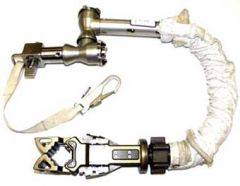
Swing Arm Assembly - right
- (picture is of a swing arm assembly right, there is also a left) - contains two bayonet receptacles per swing arm. Each bayonet receptacle is used to retain equipment and each receptacle has a slide lock to secure the equipment in the receptacle. - The swing arm assembly allows an EVA crewmember to stow hardware behind the EMU while translating and then swing the stowed hardware out in front of the EMU to retrieve the hardware. - The assembly contains a clutch mechanism that is IVA adjustable to vary the amount of force necessary to move the swing arm from behind the EMU to the front. |
|
|
General Purpose Tool Caddy
(commonly called tool caddy or shuttle tool caddy) - hard fabric container used for restraining, stowing, and transferring tools during an EVA. The shuttle tool caddies have split ring hooks or French hooks. |
|
|
Installable Handrail Carrier (IHC)
- device that provides a means for an EVA crewmember to translate the on-orbit installable worksite interfaces (OIWIFS) to the EVA worksite. |
|
|
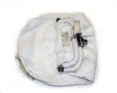
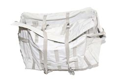
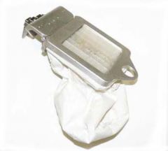
Large Trash Bag
- dual-layered container used to stow large items during an EVA. - The bag has overlapping baffles that keep small items from floating out even when the mouth of the bag is open. An adjustable strap with a quarter-turn fastener on the back can be wrapped around the MMWS stanchion for stability. - The large trash bag is secured to the MMWS via a bayonet probe. |
|
|
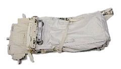
ORU Bags
- soft sided stowage bags designed to help carry ORUs and other EVA tools or equipment needed to and from a worksite. - The ORU bags come in small (-311) medium (-309) and Large (-307) sizes. -- The medium and large ORU bags have 2 internal and 2 external adjustable straps with equipment hooks which aid in the closing of the bag. -- The small ORU bag has 1 internal and 1 external adjustable synch straps. - All incorporate internal and external tether points to secure ORU in the bag. Additional straps are located on the sides of the bags to adjust the silhouette of the bags. - The ORU bags all have a dog bone handrail, micro-conical, and ECOM fitting to aid in translation and handling. |
|
|
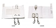
Small Trash Bag
- an assembly of mechanical components and soft goods in the form of a pouch, is used to stow small items during an EVA. - The trash bag has an opening that is covered with bristles to prevent the inadvertent release of the stowed components. - attached to the MMWS for use during EVA. - The hinge in the assembly allows the bag to be flipped up or down while the crewmember is in transition. - A tether loop on the top frame of the bag allows it to be tethered whenever it is removed from the bayonet fitting on the MMWS. - The contents of the bag are to be emptied only during IVA by opening a zippered flap in the soft goods of the bag. |
|
|
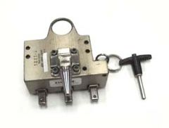
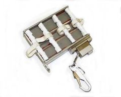
Socket Caddy
- used for storing, transporting, and tethering tools equipped with a DPT. - The socket caddy has three 3/8 inch male drive tool posts, a bayonet probe, a tether point, and a mounted retractable equipment tether with a DPT PIP pin. Note: A pull test shall be performed on sockets after installation to verify a positive connection. Operational Constraints: - Tools are operationally constrained from being stowed in a position that prevents operation of EMU controls or control of SAFER. - Caddies shall withstand an inadvertent (bump or impulse) load of 50 lb. limit load in any direction. Operational Characteristics: - The socket caddy is designed to be soft stowed, but can also be stowed via its bayonet probe. - Interface of the 3/8" male drives to the DPT are independent of orientation. - The tool post provides three detented positions of 00, 45, and 90 degrees +/- 10 degrees. The tool posts are capable of being smoothly operated between the three positions. - The socket caddy provides a retractable equipment tether (outfitted with a PIP pin). The retractable equipment tether is mounted via a base plate assembly. The fasteners provided with this assembly may or may not be used. |
|
|
Tool Caddy
- used for restraining tools during an EVA. It also provides for transferring tools to and from a worksite. - The tool caddy has a bayonet probe, a tether point, and a mounted retractable equipment tether outfitted with an equipment hook. - It is designed to be stowed in a toolbox. |
|
|
Tool Carrier Assembly
- structural unit that can carry U.S. or Russian EVA tools with bayonet probes. - The tool carrier assembly attaches to the Body Restraint Tether (BRT) end effector or the handrail end effector via a dog-bone interface. - It will also attach to the Multi-Use Tether (MUT) base or ball stack via the EVA Change Out Mechanism (ECOM) socket. - The tool carrier assembly features two retracting equipment tethers and two tether points to facilitate EVA tool transfer and usage. |
|
|
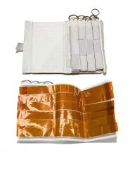
Velcro/Tape Caddy
- contingency tool to be used when Velcro or tape is needed on EVA. - The caddy consists of two flaps on each side containing; Velcro strips with D-rings on one side and Kapton strips (3 layers thick to prevent curling) on the other side. |
|
|
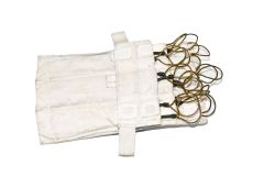
Wire Tie Caddy
- used for storing and transporting wire ties on an EVA via a bayonet fitting on the MMWS. - Wire ties are used to restrain hardware, especially wires and cables. Wire ties can be used multiple times. Note: A used wire tie may break, be aware of potential sharp edges. When filling a wire tie caddy with wire ties, keep the loops separated so that when they are retrieved EVA it is easy to tether only one end. |
|
|
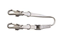
Adjustable Equipment Tether
- designed to restrain various tools and equipment, including orbital replacement units. - It is constructed of webbing with a hook at either end. The interface between the hook and the webbing is a removable pin for IVA change-out. - The tether provides a finger-actuated cam buckle which provides 10 inches of adjustment for each configuration. -- The cam buckle allows a crewmember to adjust the distance between the restraining article and the equipment to be restrained, only when the lever is depressed. - In addition, two D-rings are supplied for tether attachment points. |
|
|
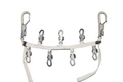
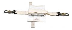
Adjustable Fuse Tether (commonly called the Fish Stringer)
- used to restrain multiple tools or items. - It consists of a Nomex strap with 7 equipment hooks spaced along its length and two large crew hooks, one at each end. - The tether also contains two cam buckles to allow for 20 inches of adjustment in the overall length. - The two large hooks are used to secure the fuse tether to the worksite or inside of an ORU transfer bag. - The 7 equipment hooks are used to tether equipment or tools. |
|
|
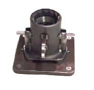
Ball Stack
- designed for temporary stowage of ORUs during EVA maintenance operations performed by a crewmember. - The ball stack has an ECOM Assembly, mounted to each end allowing it to attach to anything with an ECOM Socket. - It has an adjustable stiffness to allow for both positioning and location control during ORU change-out (location control is defined as the ability to keep the object out of the crewmembers way). - Mounting locations for the ball stack will be as follows: CETA cart, PFRWS, TERA, and Crane. |
|
|
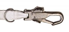
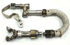
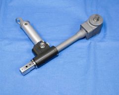
Body Restraint Tether (BRT)
- will allow a crewmember to stabilize and maintain a body position in close proximity to the worksite while retaining the use of both hands, and will also support translation with an ORU attached. - The BRT can be attached to the EMU via the modified/modular mini-workstation (MMWS), and to the Orlan via the Orlan tether adapter. - The BRT assembly is comprised of four main subassemblies: 1. base joint assembly 2. ball stack assembly 3. end effector assembly 4. equipment tether hook. - The BRT interfaces to the EMU through the MWS. Two identical MWS mounting locations (left and right side of MWS base plate assembly) are provided for BRT attachment. - The BRT interfaces to the Orlan through the Orlan tether adapter. The Orlan tether adapter mounts to the Orlan's left side. - The BRT base joint assembly, which consists of a rigid segment connected by two cone clutch joints, attaches to the interface via a ball-lock latching mechanism. The latching mechanism is located within a housing that fits over a square mount at the interface to prevent rotation. - The ball stack assembly is a flexible segment made of a series of metallic nested balls that link the end effector and the rigid segment. - At the forward end of the ball stack assembly is the end effector; the jaws are designed to grasp a dog-bone handrail or the Russian square handrail. The jaws are opened by squeezing two opposed levers. The squeeze action opens and latches the jaws in a ready-to-capture position. A trigger located inside the jaws causes the jaws to close upon contact with the handrail. When properly aligned, either on the edge or face of a handrail, the jaws will lock closed until the opposed levers are squeezed again. |
|
|
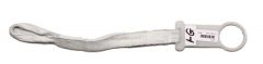
D-ring Extender
- short strap used to effectively extend the EMU D-ring further away from the suit. This makes it easier to connect to the EMU D-ring since the D-ring has limited visibility. - The crew can find the extender by using a sweeping motion with their arm. Note: If a D-ring extender is used, the safety tether load alleviating strap and the waist tether may only be on the same D-ring extender if both have locking hooks, and these hooks are in the locked position. |
|
|
ECOM (EVA Change Out Mechanism) system
- an EVA structural quick-connect/disconnect. Any EVA tool which has an ECOM socket can be mounted to any structure or EVA equipment, which has an ECOM Assembly. Note: The use of an ECOM socket to stow a tool or ORU between EVAs or missions requires approval from the ground. Operational Constraints: - Any ECOM Socket can interface with any ECOM assembly with an installation or removal force of between 2 to 10 pounds. - The ECOM Assembly has a visual indication of the locked and released positions via black-on-black and black-on-white alignment marks, respectively. - The direction toward the locked and released positions are also indicated with arrows and the words LOCK and RELEASE, respectively. |
|
|
Equipment Hooks
- EVA hook compatible with both the ORLAN-DMA and EVA EMU glove. - Opening the hook requires a pinching action and sliding of the thumb backward (accomplished single handed) to release the locking latch which opens the bail. - The equipment hook assembly will be able to interface with approved ISS and/or shuttle tether points. Note: video does not include new equipment hooks, which include a thumb lock as an added safety feature |
|
|
Gap Spanner
- a device which will be used along translation paths where no handrail exists. It will provide the crewmembers with a means to translate across these portions of the paths during EVA operations. - The gap spanner contains two separate configurations including ground and on-orbit installed configurations. - The gap spanner is constructed of 1.25 inch wide beta cloth and provides a buckle for tightening the strap for variable lengths. -- The ground installed configuration provides a loop to attach to the handhold/handrail brackets during assembly. -- The on-orbit installed configuration provides French hooks for attachment to the handhold/handrail standoffs as an EVA task. |
|
|
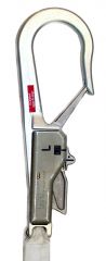
Large EVA Crew Hook
- compatible with both the ORLAN-DMA and EVA EMU glove. - Opening the hook with a single hand requires the paddles on each side to be depressed simultaneously while squeezing the operating lever. - The hook is locked by sliding the slide lock to the black-on-black position with the thumb. - The large crew hook assembly will be able to interface the oval and dog-bone cross sections of the U.S. handrail when used as an equipment tether only, and will also be able to interface with the Russian 25 mm square handrail cross section when used as a crew or equipment tether. |
|
|
Long Duration Tie Down Tether
- utilized to restrain ORUs and equipment outside of the ISS for long periods of time. - The Long Duration Tie Down Tether measures 24" to 85" in length. - Crew can pre-stretch the Long Duration Tie Down Tether in the airlock during EVA Prep to prevent unwanted stretching and loss of tension when installed. - When not using the entire length of the Long Duration Tie Down Tether, less pre-loading may be required. - Do not use the Long Duration Tie Down Tether when precise loading is required. |
|
|
Multi-Use Tether (MUT)
- designed for EVA use on the ISS for on-orbit tasks. - The MUT attaches via a tapered ball lock latching mechanism to a mounting boss on the modified mini workstation (MMWS). - The dedicated end effector allows the MUT to be attached to an EVA dog-bone or Russian handrail. - The MUT shall allow a crewmember to: -- stabilize and maintain a body position in close proximity to the worksite while retaining the use of both hands -- translate small ORUs -- facilitate in the installation and removal of an APFR at the worksite. - The MUT assembly is comprised of three main subassemblies: -- the base joint assembly, -- the ball stack assembly, -- and the end effector assembly. - Two identical mounting locations are provided for the MUT on the left and the right side of the MMWS. -- Currently, the mounting location on the right side of the MMWS has been reserved and must remain unobstructed for access to the SAFER hand controller. - The MUT base joint assembly, which consists of a rigid segment connected by two multiple-disk friction clutch joints, attaches to the MMWS via a tapered ball lock latching mechanism. The latching mechanism is located within a housing that fits over a square boss on the MMWS, preventing rotation of the MUT base joint assembly about the latching mechanism. |
|
|
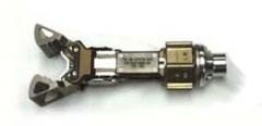
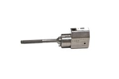
MUT End Effector
(Also known as the Handrail End Effector) - It has an ECOM (EVA Changeout Mechanism) fitting on one end, a 3/4 turn locking mechanism to lock the jaws in position, buttons on either side to open the jaws, and the jaws themselves. - The MUT EE will fit the ISS dogbone handrails from above, from the side, or from a 45° angle. However the MUT EE can be pushed out of the 45° angle position into the side or above orientations. - When combined with a ballstack and shoulder joints, the MUT EE can make a device similar to the BRT, as described above. |
|
|
Orbital Replacement Unit Tether Assembly
- designed for temporary stowage and restraint of ORUs during EVA maintenance operations. -- The ORU tether will allow the crewmember to temporarily park an ORU while installing a new ORU. - It is designed to attach to tether points via an equipment hook, and can be installed and used in three locations (the tool stanchion, the crane, and the CETA cart) with the presence of a dove tail fitting. - The ORU tether assembly is EVA installable and removable from the dove tail fitting, with the use of an EVA probe. |
|
|
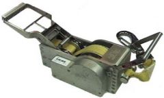
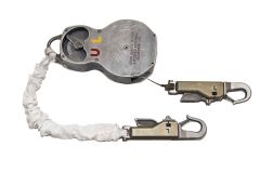
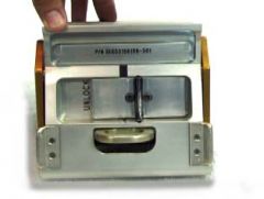
Payload Retention Device (PRD)
- used as a contingency restraint or come-along device for on-orbit use. - It consists of a webbing strap with French hooks on the ends and a stainless steel and aluminum ratchet mechanism for tightening. - The payload retention device also has a bayonet fitting for attachment to a tool stowage location with a bayonet receptacle. - The PRD can be attached with French hooks in three instances: to tether points in the cargo bay; to equipment to be secured, or to another payload retention device. - After both ends of the payload retention device are hooked in place, the crewmember pulls the handle to operate the ratchet, tightening the strap until the equipment is secure. The ratchet mechanism reels in the strap slowly enough so that the article being secured can be repositioned as necessary to prevent damage. - The payload retention device does not allow controlled release of tension. - The PRD can be attached to waist or wrist tethers, or to the mini-workstation for transport during EVA. - A patch of Velcro on the bottom of the payload retention device housing (for configuration -301 only) engages the fixed strap or hook for on-orbit restraint. |
|
|
Retractable Equipment Tether (RET) 75/30
- in various combination with hooks and PIP pins, forms the different configurations of the equipment tether 75/30. - The subassembly is composed of two basic models: a 75-pound limit load version with a slide lock and a 30-pound limit load version without a slide lock. -- The 75-pound RET is further broken down to mounted and unmounted versions (the 30-pound RET will always be mounted). -- The 30-pound RETs are mounted to other hardware via an interface plate with captive screws that allow intravehicular maintenance change out. - Configurations of the RET 75/30 are as follows: -- Mounted versions: --- With insert and with slide lock (75-pound limit) --- With insert and without slide lock (30-pound limit) --- Without insert and with slide lock (75-pound limit) -- Unmounted versions: --- With insert and with slide lock (75-pound limit) --- Without insert and with slide lock (75-pound limit) - Retractable Equipment Tethers are organized into color coded sets to aid in keeping track of the number of EVA they have been exposed to and when they need to return home for refurbishment. The sets are designated by the color of the serial number on the RET |
|
|
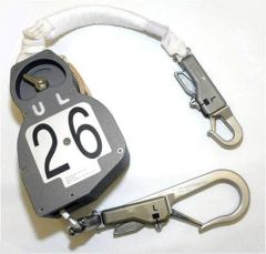
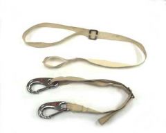
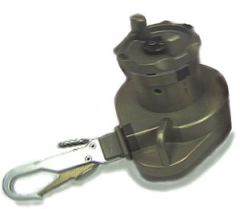
Safety Tether
- the primary means of safety restraint for EVA. - There are two lengths of safety tethers available to ISS crewmembers. The 55 foot safety tether and the 85 foot safety tether. - Each assembly consists of a reel assembly, rigid tether loop, a load alleviating tether, and crew hooks. - Both the 55 and 85 foot assemblies are available with a small crew hook on the load alleviating tether, and either a small or large crew hook on the cable end. - The space shuttle safety tether uses only small crew hooks. - Generic Operational Constraints: -- Whenever the safety tether is being connected or disconnected, the lock lever shall be in the locked position. -- Whenever the safety tether is being retracted, the lock lever shall remain in the unlocked position until retraction is complete. Internal damage may be caused to the tether if this constraint is violated. It is not a safety issue. -- Use of the large hook on the U. S. handrail in a safety tether application shall be prohibited. -- The safety tether shall be used such that a load alleviation tether is directly attached to the crewmember (an additional waist tether must be used if the crewmember is not directly attached to the load alleviation tether). -- The crewmember should avoid contact with the safety tether cable to reduce the possibility of glove damage. -- Prior to each use of the safety tether the crew should verify that the red band on the load alleviating strap has not deployed. If the red mark shows, the tether cannot be used and the tether must be returned from orbit. -- Prior to EVA use, inspect the soft goods (load alleviating strap) of the ERCM/Safety Tether for MMOD damage. The damage may appear as small or large holes in the load alleviating strap, or as a tear/rip in the Teflon cover. The MMOD damage may also appear in small concentrated areas of excessive fraying. Safety tethers used as restraints must be attached to separate handrails. -- Prior to each use of the safety tether the crew should verify that the red band on the load alleviating strap has not deployed. If the red mark shows, the tether cannot be used and the tether must be returned from orbit. -- The 85 foot safety tether can be used for ISS operations. The tether can be left external between EVAs, but not between missions. This is due to the soft good strap on the tether. - Operational Constraints (85' Safety Tether): - For Tile inspection and repair operations the 85 foot safety tether connection can be in reverse. The small crew hook on the load alleviating strap is to be attached to a waist Tether which will be attached to structure. -- When extended, the pull from the 85 foot tether may cause the BRT joints to slip. |
|
|
Tether Shuttle
- provides restrained translation of an EVA crewmember along the nadir - Mobile Transport (MT) rail. - When not in use the tether shuttle is stored on-orbit in the ISS airlock or on the ISS truss segment S0. |
|
|
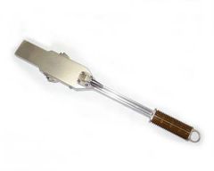
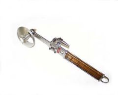
Enhanced Right Angle Drive
- transmits torque from the pistol grip tool (PGT)(or other 3/8" square male drive tools) at 90 degrees to various socket extensions with a 2:1 gear ratio. - The torque multiplication ratio is 1.6:1 to 2.0:1. - The Enhanced Right Angle Drive has a folding handle, a drop-proof tether (DPT) input, and an EVA standard, DPT compatible, 3/8" square drive output. |
|
|
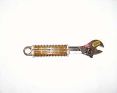
Adjustable Wrench
- a modified 10 inch crescent wrench. The jaw opening is designed to accommodate fasteners with opposing flats up to 1.125 inches. - The adjustable wrench provides a handle with low thermal conductivity to the EMU glove and a 0.75 inch tether point. |
|
|
Ball End Driver
A straight driver with an EVA handle and a 5/32-inch hex head end. The end has been rounded. |
|
|
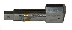
Cheater Bar
- provides an additional moment arm of 12 inches measured from a point on the common handle of the cheater bar to the same point on the interfacing tool. - The cheater bar has a bayonet probe, a standard tether point, and double soft docking spring loaded tabs that lock the cheater bar onto the hilt closest to the tether point of the interfacing tool. |
|
|
Drive Ratchet
- The 3/8 inch drive ratchet is a high torque wrench with an integral Drop Proof Tether (DPT) and a bayonet probe. - The tool has a removable palm wheel which interfaces with the ratchet through a Y male drive. - The tool is also fitted with the bilateral common handle to provide an interface with the cheater bar. - The 3/8 inch drive ratchet consists of two subassemblies: -- 1. Ratchet assembly -- 2. Palm wheel assembly Note: A pull test shall be performed on sockets and palm wheel after installation to verify a positive connection. - Operational Characteristics: -- The 3/8 inch drive ratchet is stowed in the CETA toolbox, or can also be soft-stowed for launch/landing. It is capable of interfacing with the cheater bar and the DPT. The ratchet contains: --- A bayonet probe location for stowage into a bayonet receptacle slide lock. --- A removable palm wheel that interfaces with a ¼ inch male drive to ¼ inch female drive on the ratchet. --- A 360 degree ratcheting capability in the clockwise and counterclockwise directions with the presence of a toggle switch. |
|
|
Drop Proof Tether
- The 3 inch long extension consists of an EVA standard 3/8" square female drop proof tether at one end and an American Standard 3/8" square male at the other end. The male end incorporates an IVA operable lever to provide positive lock on to EVA Certified IFM sockets. - An IFM socket is configured IVA to the DPT IFM Adapter and the adapter is configured to the standard drive tools EVA via the standard drop proof tether using a PIP-pin. - The adapter is used for EVA contingency applications and is stowed in the airlock tool bag. Note: The DPT Adapter allows an IV socket to be attached to the EVA tools. A pull test should always be performed and the socket must not be removable in at least one of its possible 4 orientations on the adapter. |
|
|
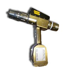
The Pistol Grip Tool (PGT)
- a self-contained, computer controlled, battery powered, 3/8" drive power tool. - The PGT may also be used as a non-powered ratchet wrench. - Torque, speed, and turn limits can be programmed into the PGT. - The PGT has a 3/8" square drive which is compatible with any Drop Proof socket, and can interface directly with the Torque Multipliers (TM) or the Crane. - The PGT is programmable with up to 14 torque settings (7 in mode A and 7 in mode B) and 6 speed settings (3 clockwise and 3 counterclockwise). - The PGT electrical system monitors and stores performance data in the Event Log which can be downloaded to the PGSC for troubleshooting purposes. - In addition to programmed torque limits, the PGT has a Multisetting Torque Limiter (MTL) with a range of settings from 2.5 to 30.5 ft-lbs. - Operational Constraints: -- To prevent damage, switch to OFF when operating PGT in ratchet mode. -- Do not ratchet with Ratchet Collar in MTR, excessive backdrive of the motor may cause damage. -- Avoid contact with the Ratchet Collar while operating PGT. Inadvertant actuation of this collar during operation in either motor or ratchet modes can cause significant internal damage to the PGT. -- Do not apply excessive side load to the output shaft. -- Do not handle PGT by an attached socket. -- Do not over tighten RS433 port door screw or the cover can be cracked. -- Use velcro strap to restrain battery D-ring to prevent snag hazard. -- Do not tether PGT by battery tether point. -- The PGT shall not be stowed via the bayonet fitting with an attached socket of greater than 6 inches in length. -- The PGT shall not be used in the interior of the Russian segment. -- During operation of the PGT multi torque limiter (MTL) it is recommended getting good complete pops. This will eliminate the problem of the MTL torque collar getting stuck when it is changed to a different setting. -- When inserting or removing the battery, the Power Switch must be in the "OFF" position. The cap ail the battery's 'D' connector is IVA only. Ensure that there is no debris in the battery connector prior to inserting the battery. -- All fasteners installation and torquing procedures will be tracked with the precise PGT serial number utilized to torque each fastener. -- Due to the increased potential of torque error at high speeds and low voltage, use of the PGT above the 45 RPM setting shall be avoided for any application where specified torque values must be held. -- The PGT shall not be handled only by the extension/socket. -- The PGT shall withstand inadvertent (bump or impulse) of 50lbs in any direction. -- Turn power off before replacing battery. - Mode and Power Switches The mode and power switches are located at the back end of the PGT. Modes are A and B and power is on/off. - Speed Collar The speed collar has 3 clockwise (CW) settings and 3 counter-clockwise (CCW) settings as well as the CAL position. All programmed speeds are given in revolutions per minute (RPM). Speeds can be programmed between 5-60 RPM. Use slower speeds with lower torque or expect a possible 10% overshoot. - Torque Collar The torque collar has 7 settings. Used in conjunction with the mode switch, this allows for up to 14 torque programs (7 in mode A and 7 in mode B). All torques are given in Foot-Pounds (ft-lb). - Ratchet Collar The ratchet collar has three settings, Ratchet Clockwise (RCW), Ratchet Counter-clockwise (RCCW), and motor (MTR). Inadvertent actuation of this collar during operation in any of these modes can cause significant internal damage to the PGT. Stabilize the PGT with a hand under the electronics housing, not on the ratchet collar. When using the PGT in MTR, the maximum allowable torque is 25.5 ft-lb and the minimum is 0.5 ft-lb. Do not ratchet in this position. The RCW and RCCW settings are for using the PGT as a manual ratchet wrench. Always switch the power off as a precaution in this manual position. Maximum allowable torque for manual ratchet operation is 30.5 ft-lb. - Multi-Setting Torque Limiter (MTL) The MTL mechanically limits the torque delivered by the output shaft. MTL settings can be changed EVA by sliding the thumb switch toward the ratchet collar and rotating the MTL collar. As a precaution, switch to RCW or RCCW before cycling the MTL to prevent backdriving the motor. - LEDs There are 4 LEDs, a green power LED, a red fault LED, and a green and a red torque LED. The power LED will remain illuminated in auto sleep mode, but will go off when the programmed auto off time is exceeded. The fault LED will illuminate for all faults and the display will show the corresponding fault message. The torque LEDs indicate the following: Red only = Under Torque, Green only = Nominal operation, Red and Green together = Over Torque. - RS422 Port The RS422 port accepts the programming cable connection. A 3/32" allen head is attched to the programming cable for use in opening the RS422 port cover. The screw should be driven partialy out such that the door can be rotated to provide access to the connector. This screw is sensitive to high torques. - Battery The PGT batteries can be changed out while EVA. Always turn the power off before changing the battery. The PGT battery is keyed to prevent incorrection insertion into the PGT. Use the velcro strap to restrain the battery D ring. Do not tether the PGT by the battery tether point. The PGT will give a low battery warning at 30 Volts and will cease operation at 28 Volts. The battery also has a polyswitch which will cease battery operation if greater than 8 amps (approx 10-15 ft-lbs) is drawn for over a 5 second period. The power must be cycled to reset the polyswitch. |
|
|
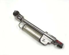
Right angle drive
- transmits torque at 90° to various socket extensions with a 2:1 input/output rotation ratio and a 1:1.2 input/output torque ratio. - The right angle drive has a folding handle, an EVA standard 3/8 inch male drive, and a DPT. Note: The Right Angle Drive has torque and RPM limitations. A new enhanced Right Angle Drive will replace the current one soon. |
|
|
|
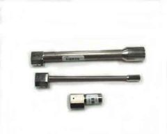
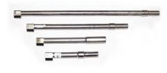
5/16" X 7" RIGID SOCKET EXTENSION
The 5/16" X 7" rigid extension has a 12 point deep well socket that interfaces with 5/16" EVA bolt heads. The socket has an integral shaft that incorporates a 3/8" Drop Proof Tether (DPT), requiring a PIP pin to mate/demate the extension to/from a 3/8" male drive. The shaft has an engraved rotation mark which acts as a guide for counting revolutions . 7/16" X 2" RIGID SOCKET EXTENSION The 7/16" X 2" rigid socket extension has a 12 point deep well socket that interfaces with 7/16" EVA bolt heads. The socket has an integral shaft that incorporates a 3/8" DPT, requiring a PIP pin to mate/demate the extension to/from a 3/8" male drive. 5/8" X 7.8" RIGID SOCKET EXTENSION The 5/8" X 7.8" rigid extension has a 12 point deep well socket that interfaces with 5/8" EVA bolt heads. The socket has an integral shaft that incorporates a 3/8" DPT, requiring a PIP pin to mate/demate the extension to/from a 3/8" male drive. The shaft has an engraved rotation mark which acts as a guide to counting revolutions. |
|
|
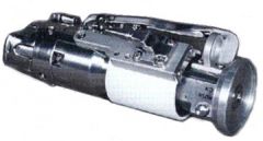
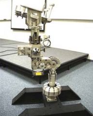
Torque Multiplier
- a tool that provides higher torque than the space station power tool can provide. - The input torque is increased by 5 times and the torque multiplier provides a torque reaction interface. - The torque multiplier has two configurations: -- one is a round (microconical) configuration and provides 7/16 and 5/8 inch interchangeable sockets and -- the second is a square configuration and provides only 7/16 inch interchangeable sockets. - The torque multiplier changeable socket set provides for the transfer of various sized sockets to and from the torque multiplier and the socket change out mechanism. The socket change out mechanism is mounted on a tool board, and provides a positive method of release and capture so that a socket will not be inadvertently released to the space environment. Socket sets are provided for the square torque multiplier and the round torque multiplier. - Round torque multiplier socket set: three sockets interfacing with a 7/16 inch proud bolt, a 7/16 inch flush bolt, and a 5/8 inch proud bolt. Square torque multiplier socket set: three sockets interfacing with a 7/16 inch proud bolt, a 7/16 inch recessed bolt, and a 7/16 inch flush bolt. |
|
|
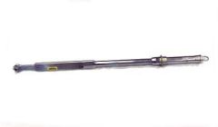
Torque wrench
- a calibrated high torque wrench with an EVA standard 3/8 inch male drive and a standard tether point. - The torque wrench has a rotating handle which is used to set the click type torque indicating mechanism. - In order to maintain accuracy, the torque wrench shall remain stowed in the torque wrench bag when not in use. The torque wrench bag has a thermal clock of 3.5 hours outside of the airlock. |
|
|
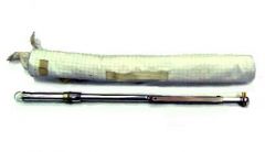
The torque wrench bag
- used as a method of stowing and transporting the bilateral torque wrench to a worksite for use during EVA, while a slotted cover in the bag provides access to the torque wrench equipment tether point. - The torque wrench bag also has integral fabric tether points. - A bayonet probe is provided for rigid attachment to the modular mini-workstation. |
|
|
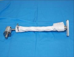
7/16" X 18" WOBBLE SOCKET EXTENSION
The 7/16" X 18" wobble socket extension has a self centering 29 degree cone angle socket that interfaces with 7/16" EVA bolt heads. The 12 point deep well wobble socket is attached to a 3/8" male drive. The shaft has an engraved rotation mark which acts as a guide to counting revolutions. 7/16" X 12" WOBBLE SOCKET EXTENSION The 7/16" X 12" wobble socket extension has a self centering 29 degree cone angle socket that interfaces with 7/16" EVA bolt heads. The 12 point deep well wobble socket is attached to a shaft that incorporates a 3/8" DPT, requiring a PIP pin to mate/demate the extension to/from a 3/8" male drive. The shaft has an engraved rotation mark which acts as a guide to counting revolutions. 7/16" X 6" WOBBLE SOCKET EXTENSION The 7/16" X 6" wobble socket extension has a self centering 29 degree cone angle socket that interfaces with 7/16" EVA bolt heads. The 12 point deep well wobble socket is attached to a shaft that incorporates a 3/8" DPT, requiring a PIP pin to mate/demate the extension to/from a 3/8" male drive. The shaft has an engraved rotation mark which acts as a guide to counting revolutions. 1/2" X 8" WOBBLE SOCKET EXTENSION The 1/2" x 8" wobble socket extension has a self-centering 29 degree cone angle that interfaces with the EFGF, FRGF, & RSGF contingency EVA release bolt heads. The 12 point deep well wobble socket is attached to a shaft that incorporates a 3/8" DPT, requiring a PIP pin to mate/demate the extension to/from a 3/8" male drive. The shaft has an engraved rotation mark which acts as a guide to counting revolutions. |
|
|
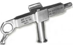
The Micrometeoroid and Orbital Debris Shield Handling Tool
also known as the MMOD Tool or T-handle Tool - has two basic functions: (1) it is used to attach or detach the MMOD shield panel sections, and (2) it is used to maneuver the MMOD shield panel sections while they are detached. -- In its first function the MMOD tool actuates ¼ turn socket-head fasteners. The allen wrench on the MMOD tool will be inserted into the allen socket on the fasteners and rotated ¼ turn to either release or attach the MMOD panel section to various ISSA modules. --as a handling tool, the MMOD tool will be used for maneuvering MMOD panel sections during EVA maintenance operations. Specifically, an EVA crewmember will use the MMOD tool to grasp, transport, and temporarily stow the MMOD panel sections. The tool design incorporates a T-handle and a hexagonal shaped probe with a locking ball detent which interfaces with hexagonal shaped sockets or receptacles, located on the MMOD panel sections. The ball detent provides a positive lock to the mating socket. |
|
|
The Articulating Portable Foot Restraint (APFR)
- designed to provide a portable platform for an EVA crewmember to temporarily secure both feet while performing assembly or maintenance tasks. Note: Crew have reported sticky pitch knob issues during space walks. Per engineering, these APRF will be used as is. Crew have also reported locking collar issues during EVA. As a workaround, crew must manually rotate the locking collar to the locked position |
|
|
The Articulating-Portable Foot Restraint lngress Aid or AIA
- a device that attaches to the APFR boot plate and incorporates a telescoping pole and standard dog-bone handle that can be used by a crewmember to ingress and egress the APFR at EVA worksites. - The AIA is designed to be installed and removed as a single-handed, free-floating EVA operation. - The attachment mechanism to the APFR provides a lock-lock feature to prevent inadvertent release from the APFR. - The AIA base attaches to the top of the APFR boot plate via a probe and socket mechanism. It includes a ball and socket joint that limits the ingress and egress loads and provides a feature which allows the crewmember to articulate the unit out of the work area and, to stow close to the boot plate for translation. - The telescoping pole can be collapsed for fold-down storage of the unit during APFR translation. |
|
|
The Interoperable Articulating Portable Foot Restraint or IAPFR
- designed for EVA use on the ISS structure, the Crew Equipment Translation Aid (CETA) cart, the Shuttle Remote Manipulator System (SRMS), and the Space Station Remote Manipulator System (SSRMS) when attached to the temporary equipment restraint aid (TERA) or latching end effector (LEE) assembly handrail. - It provides a portable platform for an EVA crewmember to temporarily secure both the EMU and the Orlan boots. - The IAPFR can articulate in the roll, yaw, and pitch by an egressed crewmember. - In addition, the IAPFR has a load-limiting device that limits the loads that can be transmitted by an ingressed crewmember into the attached structure. - The IAPFR has a dog bone handle and is transportable by a single EVA crewmember. - The IAPFR incorporates an active worksite interface (WIF) that allows it to be attached to the ISS structure or other devices, such as the TERA, that incorporate passive WIFs. |
|
|
Worksite Interface Fixture
Passive WIFs The passive halves of the WIFs (excluding the TERA passive WIF) are designed to mount to the international space station structure providing an interface for the attachment of any piece of EVA hardware that has the active WIF. The APFR and TERA are examples of pieces of EVA hardware using the active WIF. The passive WIF adapter provides a mounting interface for the APFR to a shuttle-style PFR socket. Top Mounted Passive WIF The top mounted passive halves of the WIFs provide mounting interfaces for the attachment of any piece of EVA hardware that has an active WIF. The top mounted WIFs shall incorporate internal features that allow the active WIF to be installed into soft-capture or hard-dock modes and into 12 clocking positions. Side Mounted Passive WIF The side mounted passive halves of the WIFs provide mounting interfaces for the attachment of any piece of EVA hardware that has an active WIF. The side mounted WIFs shall incorporate internal features that allow the active WIF to be installed into soft-capture or hard-dock modes and into 12 clocking positions. |