![]()
![]()
![]()
Use LEFT and RIGHT arrow keys to navigate between flashcards;
Use UP and DOWN arrow keys to flip the card;
H to show hint;
A reads text to speech;
18 Cards in this Set
- Front
- Back
|
Consider the circuit in Active Figure and assume that the battery has no internal resistance. (i) Just after the switch is closed, the potential difference across which of the following is equal to the emf of the battery? C R neither C nor R |
2. |
|
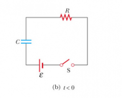
Consider the circuit in Active Figure and assume that the battery has no internal resistance. (ii) After a very long time, the potential difference across which of the following is equal to the emf of the battery? C R neither C nor R |
1. |
|
|
Kirchoff’s loop rule is an expression of conservation of a. momentum. b. charge. c. energy. d. mass. e. power. |
c. |
|
|
A non-ideal battery has a 6.0-V emf and an internal resistance of 0.6 Ω. Determine the terminal voltage when the current drawn from the battery is 1.0 A. a) 5.0 V b) 6.0 V c) 5.4 V d) 6.6 V e) 5.8 V |
c. |
|
|
Consider a circuit that contains an ideal battery and a resistor to form a complete circuit. Which one of the following statements concerning the work done by the battery is true? a) No work is done by the battery in such a circuit. b) The work done is equal to the thermal energy dissipated by the resistor. c) The work done is equal to the work needed to move a single charge from one side of the battery to the other. d) The work done is equal to the emf of the battery. e) The work done is equal to the product of the current flowing through the circuit and the resistor. |
b. |
|
|
Two 20-Ω resistors are connected in series. A potential difference of 9 V is then applied across the resistors. What is the resulting current through the resistors? a) 0.23 A b) 0.45 A c) 0.90 A d) 2.2 A e) 4.4 A |
a. |
|
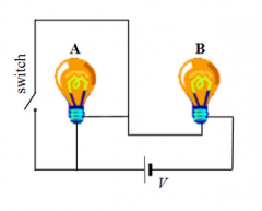
Consider the circuit shown in the drawing. Two identical light bulbs, labeled A and B, are connected in series with a battery and are illuminated equally. There is a switch in the circuit that is initially open. Which one of the following statements concerning the two bulbs is true after the switch is closed? a) Bulbs A and B will be off. b) Bulbs A and B will be equally illuminated. c) Bulb A will be brighter and bulb B will be off. d) Bulb A will be off and bulb B will be brighter. e) Both bulbs will be dimmer than before the switch was closed. |
d. |
|
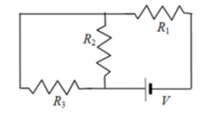
Consider the three resistors and the battery in the circuit shown. Which resistors, if any, are connected in series? a) R1 and R2 b) R1 and R3 c) R2 and R3 d) R1 and R2 and R3 e) No resistors are connected in series. |
e. |
|
|
Two 20-Ω resistors are connected in parallel. A potential difference of 9 V is then applied across both resistors. What is the resulting total current through the two resistors? a) 0.23 A b) 0.45 A c) 0.90 A d) 2.2 A e) 4.4 A |
C. |
|
Consider the three resistors and the battery in the circuit shown. Which resistors, if any, are connected in parallel? a) R1 and R2 b) R1 and R3 c) R2 and R3 d) R1 and R2 and R3 e) No resistors are connected in parallel. |
C. |
|
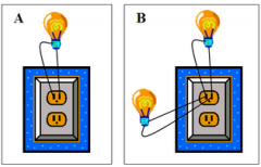
Consider the circuits shown in parts A and B in the picture. In part A, a light bulb is plugged into a wall outlet that has a voltage of 120 volts. A current i passes through the circuit and the bulb turns on. In part B, a second, identical light bulb is connected in parallel in the circuit. How does the total current in circuit B compare with that in circuit A? a) The current is the same, i, as in part A. b) The current is twice as much, 2i, as in part A. c) The current in part B is zero amperes. d) The current is one fourth as much, 0.25i, as in part A. e) The current is one half as much, 0.5i, as in part A. |
B. |
|
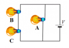
Consider the three identical light bulbs shown in the circuit. Bulbs B and C are wired in series with each other and are wired in parallel with bulb A. When the bulbs are connected to the battery as shown, how does the brightness of each bulb compare to the others? a) Bulbs B and C are equally bright, but bulb A is less bright. b) Bulbs B and C are equally bright, but less bright than bulb A. c) All three bulbs are equally bright. d) Bulbs A and B are equally bright, but bulb C is less bright. e) Only bulb A is illuminated. |
B. |
|
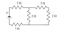
What is the approximate equivalent resistance of the five resistors shown in the circuit? a) 21 Ω b) 7 Ω c) 11 Ω d) 14 Ω e) 19 Ω |
D. |
|
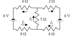
Which one of the following equations is not correct relative to the other four equations determined by applying Kirchoff’s Rules to the circuit shown? a) I2 = 1 + I4 b) I2 = I3 + I5 c) 6 V − (8 Ω) I1 − (5 Ω) I2 − (4 Ω) I3 = 0 d) 6 V − (6 Ω) I4 − (5 Ω) I2 − (2 Ω) I5 = 0 e) 6 V − (8 Ω) I1 − (6 Ω) I4 − 6 V − (2 Ω) I5 − (4 Ω) I3 = 0
|
e. |
|
|
What effect, if any, does increasing the battery emf in an RC circuit have on the time to charge the capacitor? a) The charging time will decrease because the rate of charge flowing to the plates will increase. b) The charging time will decrease because the rate of charge flowing to the plates will decrease. c) The charging time will not change because the charging time does not depend on the battery emf. d) The charging time will increase because the emf is increased. e) The charging time will decrease because potential difference across the plates will be larger. |
c. |
|
|
The resistance in an RC circuit is comprised of a 1.5-MΩ resistor in parallel with a 2.0-MΩ resistor. What is the time constant for this circuit if the capacitance is 2.5 µF? a) 2.0 s b) 7.0 ms c) 5.0 µs d) 120 s e) 4000 s |
a. |
|
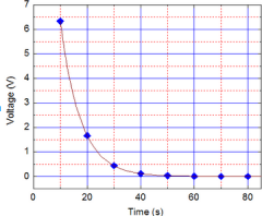
In physics lab, Rebecca measured the voltage across an unknown capacitor in an RC circuit, every ten seconds after a sw itch in the circuit that allows the capacitor to discharge is closed. The capacitor was initially fully charged. Using the graph, estimate the time constant. a) 7.5 s b) 15 s c) 30 s d) 45 s e) 60 s |
a. |
|
|
An uncharged 5.0-µF capacitor and a resistor are connected in series to a 12-V battery and an open switch to form a simple RC circuit. The switch is closed at t = 0 s. The time constant of the circuit is 4.0 s. What is the charge on either plate of the capacitor after one time constant has elapsed? a) 7.4 × 10⁻⁵ C b) 5.5 × 10⁻⁵ C c) 1.2 × 10⁻⁵ C d) 3.8 × 10⁻⁵ C e) 2.2 × 10⁻⁵ C |
d. |