Reading...
![]()
Play button
![]()
Play button
![]()
Use LEFT and RIGHT arrow keys to navigate between flashcards;
Use UP and DOWN arrow keys to flip the card;
H to show hint;
A reads text to speech;
184 Cards in this Set
- Front
- Back
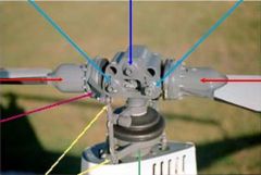
light blue arrow
|
coning hinges
|
|

dark blue arrow
|
teeter hinge
|
|

red arrows
|
blade grips
|
|

pink arrow
|
blade pitch change horn
|
|

yellow arrows
|
pitch link
|
|

green arrow
|
swash plate
|
|

yellow arrows
|
pitch link
|
|
|
Attaches the rotor blade to the rotor head and includes a pitch change mechanism used to change angle of attack by feathering the blade (with the cyclic control) has multiple bearings, and is filled with a fluid similar (identical?) to automatic transmission fluid.
|
Blade Grips
|
|
|
major components of a helicopter 7
|
1 - cabin 2 - airframe 3 - landing gear 4 - powerplant 5 - transmission 6 - main
rotor system 7 - tail rotor system |
|
|
torque
|
tendency of the helicopter to turn in the direction opposite the main rotor direction
|
|
|
The purpose of the __ ___ and __ is to absorb the acceleration and deceleration of the rotor
blades |
drag hinge and dampers
|
|
|
the purpose of the antitorque rotor is to
|
produce thrust to oppose torque and helps prevent the helicopter from turning in the opposite direction of the main rotor
|
|
|
the engine drives the __ __ through a transmission and belt drive or centrifugal clutch system
|
main rotor
|
|
|
The antitorque rotor is driven from the
|
transmission
|
|
|
The engine drives the __ __ which then transfers power directly to the main rotor system as well as the tail rotor
|
main transmission
|
|
|
above __ feet throttle correlation and governor are less effective - power changes should be slow and smooth
|
4000
|
|
|
at __ power settings above 4000 feet the throttle is frequently __ open and __ must be controlled with collective
|
high wide RPM
|
|
|
the governor is only active above __ % engine RPM
|
80
|
|
|
when operating at high density altitudes governor response rate may be __ __ to prevent overspeed during gusts pullups or when lowering collective
|
too slow
|
|
|
never exceed airspeed Vne
|
up to 3000 ft density altitude-102 KIAS
|
|
|
max rotor speed
|
tach 104%-RPM 530
|
|
|
max engine speed
|
2652 RPM 104%
|
|
|
max cylinder head temperature
|
500 degrees F (206 degrees C)
|
|
|
max oil temperature
|
245 degrees F (118 degrees C)
|
|
|
oil pressure min during idle
|
25 psi red beginning
|
|
|
oil pressure min during flight
|
55 psi middle yellow
|
|
|
oil pressure max during flight
|
95 psi red
|
|
|
oil pressure max during start and warmup
|
115 psi red
|
|
|
max gross weight
|
1370 lb (622 kg)
|
|
|
min gross weight
|
920 lb (417 kg)
|
|
|
max per seat plus baggage compartment
|
240 lb (109 kg)
|
|
|
max in baggage
|
50 lb (23 kg)
|
|
|
min solo weight __ lbs with __ fuel or __ lbs with aux fuel
|
130 standard 135
|
|
|
datum line is __ inches forward of main rotor shaft centerline
|
100
|
|
|
prohibited ___flight
|
aerobatic
|
|
|
prohibited __ cyclic __
|
low-g pushovers
|
|
|
prohibited ___ selected off with exceptions of __
|
governor-(system malfuntion or emergency procedures training)
|
|
|
prohibited __ conidtions
|
icing
|
|
|
prohibited-max operating density altitude
|
14000 ft
|
|
|
prohibited-operational gages required for flight
|
alternator-rpm governor-low rotor rpm alarm-oat
|
|
|
solo flight from __ seat only
|
right
|
|
|
__ seat belt must be buckled
|
left
|
|
|
minimum crew is __ pilot
|
one
|
|
|
no loose items allowed in cabin during ___ flight
|
doors-off
|
|
|
lights required for VFR operation at night 4
|
1 landing 2 navigation 3 instrument 4 anticollision
|
|
|
grade of fuel
|
100 ll (low lead) light blue
|
|
|
mixing wrong types of fuel will cause the resulant fuel to change color to
|
white
|
|
|
main tank total capacity
|
198 gallons (75 liters)
|
|
|
main tank usuable capacity
|
192 gallons (73 liters)
|
|
|
aux tank total capacity
|
109 gallons (41 liters)
|
|
|
aux tank usuable capacity
|
105 gallons (40 liters)
|
|
|
airspeed indicator green arc
|
50 to 102 KIAS
|
|
|
airspeed indicator red line
|
102 KIAS
|
|
|
rotor tach upper red line
|
110%
|
|
|
rotor tach yellow arc
|
104 to 110%
|
|
|
rotor tach green arc
|
101 to 104%
|
|
|
rotor tach yellow arc
|
90 to 101%
|
|
|
rotor tach lower red line
|
90%
|
|
|
rotor tach yellow arc
|
60 to 70%
|
|
|
engine tach upper red arc
|
104 to 110%
|
|
|
engine tach green arc
|
101 to 104%
|
|
|
engine tach lower red arc
|
90 to 101%
|
|
|
engine tach yellow arc
|
60 to 70%
|
|
|
oil pressure lower red line
|
25 psi
|
|
|
oil pressure lower yellow arc
|
25 to 55 psi
|
|
|
oil pressure green arc
|
55 to 95 psi
|
|
|
oil pressure upper yellow arc
|
95 to 115 psi
|
|
|
oil pressure upper red line
|
115 psi
|
|
|
oil temperature green arc
|
75 to 245 degrees f (24 to 118 degrees C)
|
|
|
oil temperature red line
|
245 degrees F (118 degress C)
|
|
|
Cylinder head temperature green arc
|
200 to 500 F (93 to 260 C)
|
|
|
Cylinder head temperature red arc
|
500 F (260 C)
|
|
|
manifold pressure yellow arc
|
19.6 to 24.1 in Hg
|
|
|
manifold pressure red line
|
24.1 in Hg
|
|
|
carburetor air temperature yellow arch
|
-15 to 5 C
|
|
|
below 18 in manifold pressure
|
ignore gage and apply full carb heat
|
|
|
prohibited solo flight when surface winds exceed __ knots
|
25 gusts
|
|
|
prohibited solo flight when surface wind gust spreads exceed __ knots
|
15 knots
|
|
|
prohibited flight turbulences 3
|
1 moderate 2 severe 3 extreme
|
|
|
upon encountering turbulence adjust forward airspeed to between __ knots and __ Vne but no lower than __ knots
|
60 07 57
|
|
|
moderate causes changes in 3
|
1 altitude or attitude 2 variations in indicated airspeed 3 strain against the seat belts
|
|
|
Main Rotor - Articulation
|
free to teeter and cone-rigid inplane
|
|
|
main rotor-tip speed
|
approx 100% RPM - 672 FPS
|
|
|
tail rotor - articulation
|
free to teeter - rigid inplane
|
|
|
tail rotor-tip speed
|
approx 100% RPM - 599 FPS
|
|
|
drive system - engine to upper sheave
|
two double vee-belts with 85361 speed reducing ratio
|
|
|
drive system - upper sheave to drive line
|
sprag type overrunning clutch
|
|
|
drive system - drive line to main rotor spiral-bevel gears with
|
1147 speed reducing ratio
|
|
|
drive system - drive line to tail rotor spiral-bevel gears with
|
32 speed increasing ratio
|
|
|
powerplant model
|
0-360-J2A
|
|
|
normal rating _ BHP (derated)approx __ RPM
|
145 2700
|
|
|
max continuous rating __ BHP approx __ RPM Tach percent __
|
124 2652 104%
|
|
|
5 minute takeoff rating __ BHP __ RPM
|
131 2652
|
|
|
main rotor system is able to
|
Flap and Feather
|
|
|
4 Cone Dimensions
|
1 - SemiRidgid 2 - Underslung 3 - Asymetrical (w/ Twist) 4 - 25'2 Diameter
|
|
|
Electrical System
|
-12 Volt Battery- 60 Amp/14 Volt Alternator
|
|
|
KIAS
|
knots indicated airspeed
|
|
|
KCAS
|
knots calibrated airspeed-corrected for instrument and position error
|
|
|
KTAS
|
knots true airspeed-airspeed relative to undisturbed air-KCAS corrected for pressure altitude and temperature
|
|
|
Vne
|
never-exceed airspeed
|
|
|
Vy
|
speed for best rate of climb
|
|
|
msl altitude
|
set to the atmospheric pressure at sea level
|
|
|
pressure altitude
|
when the barometric subscale is set to 29.92 inches of mercury (10132mb)
|
|
|
density altitude
|
in (ISA) International Standard Atmosphere conditions at which the air would have the same density (it is the pressure corrected for (OAT) outside air temperature
|
|
|
ISA
|
international standard atmosphere-sea level 29.92 temp 15 degrees and temp decreases 198 degress per 1000 ft of altitude
|
|
|
BHP
|
brake horsepower is the actual output of the engine
|
|
|
MAP
|
manifold pressure is the absolute pressure in inches of mercury in the engine intake manifold
|
|
|
MCP
|
maximum continuous power
|
|
|
TOP
|
takeoff power-continuous of 5 minutes
|
|
|
msl altitude
|
set to the atmospheric pressure at sea level
|
|
|
pressure altitude
|
when the barometric subscale is set to 2992 inches of mercury (10132mb)
|
|
|
density altitude
|
in (ISA) International Standard Atmosphere conditions at which the air would have the same density (it is the pressure corrected for (OAT) outside air temperature
|
|
|
critical altitude
|
altitude at which full throttle produces maximum allowable power (MCP or TOP)
|
|
|
TOGW
|
takeoff gross weight
|
|
|
OAT
|
outside air temperature
|
|
|
CAT
|
caburetor air temperature
|
|
|
CHT
|
cylinder head temperature
|
|
|
GPH
|
gallons per hour
|
|
|
AGL
|
above ground level
|
|
|
IGE
|
in ground effect
|
|
|
OGE
|
out of ground effect
|
|
|
ALT
|
alternator
|
|
|
reference datum
|
an imaginary vertical plane from which all horizontal distances are measured for balance purposes
|
|
|
station
|
a fore-and-aft location along the helicopter fuselage usually given in terms of distance in inches from the reference datum
|
|
|
moment
|
the product of the weight of an item multiplied by its arm
|
|
|
center of gravity
|
the point at which a helicopter would balance if suspended
|
|
|
cg arm
|
the arm from the reference datum obtained by adding the helicopter's individual moments and dividing the sum by the total weight
|
|
|
cg limits
|
the exteme center of gravity locations within which the helicopter must be operated at a given weight
|
|
|
usable fuel
|
fuel available for flight planning
|
|
|
ususable fuel
|
fuel remaining after a runout test has been completed in accordance with governmental regulations
|
|
|
standard empty weight
|
weight of a standard helicopter including unusable fuel-full operating fluids-and full oil
|
|
|
basic empty weight
|
standard empty weight pule weight of installed optional equipment
|
|
|
payload
|
weight of occupants- cargo- and baggage
|
|
|
useful load
|
difference between maximum takeoff weight and basic empty weight
|
|
|
POH Emergency
|
POH Emergency
|
|
|
Land Immediately
|
Land On The Nearest Clear Area
|
|
|
2 Land Immediately
|
Where A Safe / Normal Landing Can Be Performed- Be Prepared To Auto
|
|
|
2 Land As Soon As Practical
|
1 - Land @ The Nearest Airport Or Facility 2 - Where Emergency Maintainence Can Be Performed
|
|
|
2 Power Failure General May Be Caused By
|
1 - Engine Failure or 2 - Drive System Failure
|
|
|
5 Engine Failure Symptoms
|
1 - Left Nose Yaw 2 - Change In Noise Level 3 - Low H/L Warning 4 - Oil Light 5 - Tachs
|
|
|
4 Drive System Failure Symptoms
|
1 - Unusual Noise 2 - Right/Left Nose Yaw 3 - Low Rotor RPM 4 - High Engine RPM (Wined Up)
|
|
|
6 Power Failure @ 500 ft AGL Procedures
|
1 - Immediate Down Collective/Maintain Rotor RPM/enter auto 2 - Establish A Steady Glide/About 65 KIAS 3 - Adjust Collective/Keep Rotor RPM In Green Arch 4 - Choose A Landing Area/Maneuver Into Wind If Alt Permits 5 - Restart or No Restart 6 - Raise Collective Just Before Impact/To Cushion Landing (Touchdown In Level Attitude)
|
|
|
if power failure occurs at night-dont turn on __ __ above 1000 ft AGL to preserve battery power
|
landing lights
|
|
|
5 Restart Procedure
|
1 - Mixture Full Rich 2 - Primer Down/Locked 3 - Throttle Closed 4- Then Slightly Cracked4 5 - Actuate Starter w/ Left Hand
|
|
|
2 No Restart procedure
|
1 - Turn Off All Unnecessary Switches 2 - Shut Off Fuel
|
|
|
2 Landing @ 40' AGL
|
1 - Start Cyclic Flare 2 - To Reduce ROD & FWD Airspeed
|
|
|
2 Landing @ 8' AGL
|
1 - FWD Cyclic 2 - To Level Ship
|
|
|
7 Power Failure Between 8' & 500' AGL
|
1 - Takeoff Should Be Conducted-Per Hight/Velocity Diagram 2 - Immediate Down Collective-Maintain Rotor RPM 3 - Adjust Collective-Keep Rotor RPM In Green Arch 4 - Maintain Airspeed Until Ground Approaches 5. As Ground Approaches-Start Cyclic Flare To Reduce ROD & FWD Airspeed 6. @ 8' AGL-FWD Cyclic To Level Ship 7. Raise Collective Just Before Impact
|
|
|
3 Power Failure Below 8' AGL
|
1. Immediate Right Pedal-To Prevent Yaw 2. Allow Aircraft To Settle 3. Raise Collective Just Before Impact
|
|
|
Max Glide Configuration
|
- 90% Rotor RPM - 75 KIAS
|
|
|
4 Ditching Power Off
|
1 Follow Same Procedures As Over Land Power Failure-Until Water Contact 2 Apply Lateral Cyclic-To Stop Blades 3 Release Seat Belts 4 Clear Aircraft
|
|
|
11 Ditching Power On
|
1 Descend To Hover Above Water 2 Unlatch Doors 3 Allow Passengers To Exit 4 Fly To Safe Distance For Passengers 5 Switch Off-Master Battery & Alternator 6 Roll Off Throttle 7 Keep Level / Allow Aircraft To Settle 8 Pull Full Collective On Water Contact 9 Apply Lateral Cyclic-To Stop Blades 10 Release Seat Belts 11 Clear Aircraft
|
|
|
Loss Of Tail Rotor Thrust In Forward Flight symptoms
|
1 - Indicated By A Right Nose Yaw 2 - Can Not Be Corrected By Left Pedal
|
|
|
5 Loss Of Tail Rotor Thrust In Forward Flight
|
1 Immediately Enter Autorotation 2 Maintain @ Least 70 KIAS 3 Select Landing Site 4 Roll Off Throttle 5 Perform Autorotation Landing
|
|
|
2 Loss Of Tail Rotor Thrust During Hover Symptoms
|
1 - Indicated By A Right Nose Yaw 2 - Can Not Be Corrected By Left Pedal
|
|
|
3 Loss Of Tail Rotor Thrust During Hover
|
1 Roll Off Throttle 2 Allow Aircraft To Settle 3 Raise Collective Just Before Impact
|
|
|
5 Engine Fire During Start at Ground (Engine Starts)
|
1 - Continue Cranking/10 to 15 seconds 2 - Run @ 50% To 60% For A Short Time 3 - Shut Down 4 - Extinguish 5 - Inspect
|
|
|
5 Engine Fire During Start at Ground (Engine Doesn't Start)
|
1 - Continue Cranking/10 to 15 seconds 2 - Shut Off Fuel 3 - Shut Off Master Battery 4 - Extinguish 5 - Inspect
|
|
|
7 Engine Fire In Flight (Smells like something burnt)
|
1 - Immediately Enter Auto 2 - Master Battery Off 3 - Cabin Heat Off 3 - Cabin Vent Open 4 - Engine On/Normal Landing or Engine Off/Autorotational Landing 5 - Shut Off Fuel 6 - Extinguish 7 - Inspect
|
|
|
4 Electrical Fire In Flight
|
1 - Master Batter Off 2 - Alternator Off 3 - Land Immediately 4 - Extinguish/Inspect
|
|
|
During and Electrical Fire In Flight what two systems will be inoperative with master battery and alternator switches off
|
Governor and Low RPM Warning System
|
|
|
Tach Failure (1 Of 2 Tachs Fail)
|
Use Remaining Tach
|
|
|
2 Both Tachs Fail
|
1 - Use Governor 2- Land As Soon As Practical
|
|
|
Each tach-the governor-and the low RPM warning horn are on
|
separate circuits
|
|
|
Either the battery or the alternator can __ supply power to the tachs
|
independently
|
|
|
A special circuit allows the battery to supply power to the tachs even if the __ __ __ is off
|
master battery switch
|
|
|
3 Governor Failure
|
1 - Grip Throttle Firmly 2 - Switch Gov Off 3 - Complete Flight w/ Manual Throttle Control
|
|
|
4 Oil Pressure Light
|
1 - check engine tach for power loss 2 - Check oil pressure Gauge 3 - If Pressure Loss 4 - Land Immediately
|
|
|
MR (Main Rotor) Temp
|
indicates excessive temp of MR gearbox - land immediately if noise vibration or temp rise
|
|
|
MR (Main Rotor) Chip
|
indicates metallic particles in MR gearbox - land immediately if noise vibration or temp rise
|
|
|
TR (Tail Rotor) Chip
|
indicates metallic particles in TR gearbox - land immediately if noise vibration or temp rise
|
|
|
Low fuel light warning light
|
indicates approx one gallon of usable fuel remaining - will run out after five minutes at cruise power
|
|
|
Clutch LightLess Than 7 Seconds
|
Ignore - never take off with clutch light on
|
|
|
4 Clutch light on more Then 7 Seconds
|
1 - Pull Clutch Circuit Breaker 2 - Land Immediately 3 - Be Prepared To Auto 4 - inspect for malfunction
|
|
|
Alternator (ALT)
|
indicates low voltage and possible alternator failure
|
|
|
Alternator (ALT) steps
|
1 - turn off nonessential electrical equip 2 - switch ALT off and back on after on second to reset overvoltage relay 3 - land as soon as possible
|
|
|
Flight without functioning alternator results
|
in loss of electronic tachometer
|
|
|
Brake warning light
|
rotor brake engage-disengage
|
|
|
Starter On warning light
|
1 - immediately pull mixture to idle cut-off 2 - turn master switch off 3 - have starter motor serviced
|
|
|
4 carbon monoxide light (if installed)
|
1 - open nose and door vents 2 - shut off heater 3 - if hovering-land or transition to forward flight 4 - CO symptoms persist-land immediately
|
|
|
LOW RPM horn warning light
|
1 - restore RPM by rolling throttle on 2 - lower collective 3 - in forward flight/apply aft cyclic
|
|
|
2 Right roll in low G condition
|
1 - gradually apply aft cyclic to restore positive G forces and MR thrust 2 - dont apply lateral cyclic until positive G forces are established
|
|
|
2 uncommanded pitch-roll-or yaw resulting from flight in trubulence
|
1 - gradually apply controls to maintain rotor RPM-positive Gs-elminate sideslip 2 - minimize cyclic control inputs/dont overcontrol
|
|
|
3 inadvertent encounter with mod/severe/extreme turbulence
|
1 - depart area if isolated 2 - land as soon as practical
|