![]()
![]()
![]()
Use LEFT and RIGHT arrow keys to navigate between flashcards;
Use UP and DOWN arrow keys to flip the card;
H to show hint;
A reads text to speech;
76 Cards in this Set
- Front
- Back
- 3rd side (hint)
|
What is the purpose of the AC electrical distribution? |
To generate and transmit electrical power for distribution to the ComEs system and to provide a reliable source of power for the stations electrical auxiliaries |
Slide 22 of power point |
|
|
What criteria is required to meet the independence and redundancy requirements of the ESF systems |
Maximum physical separation of components and maximum electrical separation of components |
|
|
|
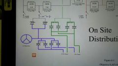
What are the 10 subsystems for the AC distribution system |
345kv ring bus Main Transformer System Aux Transformers Main Generator Isolated Phase Bus conductors and cooling ducts Unit Aux Transformers 6900 vac (6.9kv) 4160 vac (4kv) 480 vac 125 volt instrument busses |
There are 10 sub systems |
|
|
What is the ESF system single failure criterion? |
A single failure including a complete loss of power to one ESF division, will not affect the remaining ESF division |
|
|
|
How is the single failure criterion accomplished? |
Redundant ESF power supplies Redundant ESF loads and Automatic protection and isolation of system faults. |
There are 3 |
|
|
How many system decisions does each unit have |
Two |
|
|
|
Tranformer numbering what do the first second and third and the fourth numbers mean |
First # is the unit number Second and Third# is the transformer number Fourth # is the sequential number (odd numbers supply odd numbered busses) |
This is not a test question but a comprehension card |
|
|
What are the voltage levels associated with the second digit on a Bus component number |
5=6900V (6.9kv) 4=4160V (4kV) 3=480V 2=250Vdc 1=110 to 125 Vac or Vdc |
This is a comprehension question not a test question |
|
|
What is the design basis for the a.c. electrical distribution system |
Designed to provide a diversity of reliable power sources which are physically and electrically isolated so that any single failure will affect only one source of supply and will not propagate to alternate sources. |
|
|
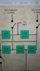
What bus is between the two breakers ACB 9-10 and OBC 10-11? How can you tell? |
Bus 10, the common digit between them is 10. |
This is comprehension from Chest hair |
|
|
Which type of circuit breaker is air to close and spring to open? |
Oil cooled circuit breaker. |
|
|
|
Which type of circuit breaker has a motor operated disconnect versus a manually operated disconnect? |
Air circuit breakers have the motor operated. Oil circuit breakers have the manuals. |
|
|
|
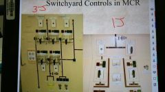
What type of switches are in the control room for the switchyard controls? |
Keyed switches |
|
|
|
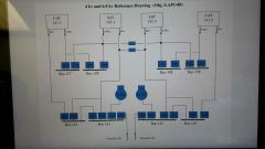
What are the special features of the AC system? This includes the added benefit of a ring bus design. |
Local breaker backup, Auto Recloser, Main Generator Second Sync check enables Ring bus design allows the isolation of busses without the whole unit coming offline. |
|
|
|
What is the 50/2 device local breaker back-up (LBB) |
The 50/2 LBB timer is energized any time the breaker is called upon to trip by a protected relay. If the breaker fails to trip within 10 cycles the 50/2 willenergize the 86 LBB relay. Key takeaway is the 50/2 LBB initiates the 86 LBB |
|
|
|
What is the 86 LBB (local breaker back-up) |
86 LBB is a lock out device for a Bus. It is activated by the 50/2 and will have an Amber light over it. |
|
|
|
79 Reclosure Device has two types what are they and what does this device do? |
Reclosure Dead Timed (RDT) and Reclosure Alive Synchrocheck Timed (RAST) The 79 Reclosure Device will try to reopen the breaker one time after is sees that the fault is cleared in the event of a transient that causes a fault. |
|
|
|
79 Reclosure device- what is the difference between the RDT and RAST types? |
RDT- the Reclosure device acts to reclose the breaker of the line is deenergized and the fault is cleared within 60 seconds of receiving the trip. RAST-this type of reclosure is equipped with a time delay which acts to close the breaker only after the line has been deenergized for at least 1 second. |
|
|
|
What feeds the UATs (Unit Aux Transformers) |
The Main Power Transformers (MPTs) |
|
|
|
What do the Westinghouse and Siemens Main Power Transformers have in common? |
Both are: Connected to the 23.7kV output of the main generator via isolated bus and duct coolers Consist of 2 transformers Each transformer has a half capacity Unit side is isolable through the use of removable bus links Connected in parallel 2 winding step up transformer (primary [23.7kV]-delta & secondary [345kV]- grounded 'Y') Differences lie within the cooling of the transformer. |
|
|
|
What can cause a Main Transformer Trip? |
D-Differential Current D-Differential Current Backup N-Neutral Ground Overcurrent O-Over-Excitation B-Bus Overcurrent (U1-8/U2-10) S-Sudden Pressure Relay |
|
|
|
What can activate the fire deluge System? |
Differential current and sudden pressure. |
Bothfaults may occur as a result of a possible oil fire. |
|
|
What is the purpose of a SAT (system/station auxiliary Transformer)? |
The SATs are used to supply power to the unit during startup, shutdown and hot standby One SAT is sufficient to supply the units peak power demand. SATs are the normal power supply to the 4160 V(aka 4kV) ESF busses (141 and 142) Normal ops the plants auxiliary loads are split between the UATs and SATs. |
|
|
|
What are the two secondary windings and the one primary winding of the SATs? |
Secondary: 6.9kV which supplies power at 6.9kV (duh) to the Non ESF busses.
4kV which supplies power at 4kV to both ESF and/or Non ESF busses.
Primary: Powered by the ring bus section 4(14) at 345kV |
|
|
|
What happens when a SAT trips to the other power lines and what are the causes of a SAT trip? |
SAT trips causes 345kV switchyard breakers feeding the SAT bus to open, and SAT feed breakers to 6.9kV and 4kV buses to open.
Can trip on: D-Differential Current O-Overcurrent N-Neutral Ground Overcurrent S-Sudden Pressure Relay B4-Bus Overcurrent (U1-4/U2-14) |
Richard Morgan sucksat teaching. |
|
|
What is the purpose of a Unit Auxiliary Transformer? |
The UATs are similar to the SATs. One UAT is suffcient enough capacity to supply the units peak power demand. The plants aux loads are split between the UATs and the SATs during normal power operation. They are not available when the main generator is secured. |
|
|
|
What are the two secondary windings and the one primary winding of the UATs? |
Secondary: 6.9kV supplies power to the nonESF busses 4kV supplies power to the nonESF busses. Primary: The primary winding is powered from the output of the main generator at 23.7kV. |
|
|
|
What happens when a UAT trips to the other power lines and what are the causes of a UAT trip? |
When UAT trips it causes a Main Generator trip. It trips on: D-Differential Overcurrent O-Overcurrent N-Neutral Ground Overcurrent S-Sudden Pressure Relay |
|
|
|
How to isolate a faulted UAT |
The Main Generator is tripped which results in a loss of both UATs and the UATs feed the Non safety related systems on the 6.9 and 4KV lines. The primary side of each UAT is isolable through the use of removable bus links. |
|
|
|
What needs to happen (switch on/off and breaker open/close) to close a ring bus breaker via control room interlocks? |
0PM03J- Sync switch-ON MPT disconnects-OPEN C/S-CLOSE
_PM01J(Gen. Output Breakers only) Sync switch-ON Synchrocheck relay-SATISFIED Bus 8 or 10 must be energized from the main generator via the MPT disconnects C/S-CLOSE |
|
|
|
ACB(air circuit breaker) trip/interlocks |
Busses 8 or 10 MO(Motor Operated) disconnects auto-open when the ACB is open and air pressure fails low. This feature is bypassed is the ACB is already shut. |
|
|
|
What can cause an automatic trip on a ring bus breaker? |
Line fault LBB 86G1A/86G1B (Main Generator Trip relays) energized to trip Generator Output Breakers SAT faults to trip SAT breakers ACB 3-4 OCB 4-7. |
|
|
|
What can cause a manual trip of a ring bus breaker? |
0PM03J (C/S to trip) _PM01J-C/S to trip and trip permissive is activated-Reverse Power C/S-"Pull out" (either panel) |
|
|
|
6.9kV supplies power to what type of equipment and is powered from what? |
It power non-ESF equipment (2250 HP to 11000HP) and the 6.9kV is supplied power from either a system Aux transformer or a Unit Aux transformer. |
|
|
|
During normal lineup the 1/258, 1/259 buses are powered from which transformers? |
158 and 159 are powered from UAT 142-2 and 142-1 respectively. 258 and 259 are powered from 242-2 and 242-1 respectively. |
|
|
|
What loads does the 156 Bus carry? |
B RCP, B Heater Drain Pump, A Feedwater motor driven pump |
BBA |
|
|
What loads does the 157 Bus carry? |
A RCP, A Heater Drain Pump, C Heater Drain Pump. |
AAC |
|
|
What loads does the 158 Bus carry? |
C RCP, B Condensate/Condensate booster pump, D Condensate/Condensate booster Pump |
CBD |
|
|
Bus 159 carries what loads? |
D RCP, A Condensate/Condensate booster pump, C Condensate/Condensate booster pump |
DAC |
|
|
Why are the C and D RCPs powered from a SAT? |
To preclude the loss of pressurizer spray on the event of an ABT (Auto Bus Transfer) failure because spray originates from the C and D RCS loops. |
|
|
|
Why is there a concern with under voltage or under frequency condition in the 6.9kV bus? |
Because the 6.9kV buses supply power to the RCPs and the loss can cause a DNBR issue. It would cause a reactor trip (5268V (76%) for >=0.8 seconds on 2/4 or more RCP buses and reactor turbine power is greater than 10% (P-7)) |
|
|
|
6.9kV under frequency does what to RCPs? |
As freq drops RCP pump speed drops As pump speed drops, pump flow drops (duh) As flow drops through the core a DNBR of less than 1.3 could be reached.
The less than 1.3 DNBR is prevented by a reactor trip if: 57.0Hz for >=0.4seconds, 2/4 or more RCP busses and power is greater than 10% (P-7). |
|
|
|
Breaker operating thumb rules |
1) Must have a good source (no SAT/UAT faults) 2) Must have a good bus to feed. (no bus lockouts) 3) Can't crosstie the unit 1 SAT to the unit 2 SAT 4)Must meet auto or manual closing logic (ABT logic, DG output breaker interlocks, sync scope interlocks) 5) Can't backfeed ESF from Non-ESF bus or Non-ESF bus from other unit. |
|
|
|
What powers the 4KV bus? |
Non ESF powered from: SAT, UAT, And/or corresponding ESF bus (i.e. 143 from 141 via 1411) ESF is powered from: SAT, Emergency Diesel Generator, Corresponding ESF bus of the opposite unit (ie 141 from 241 via 1414 and 2414). |
|
|
|
What are the 5 breaker operating thumb rules? |
1) Must have a good power source (no faults in SAT or UAT) 2) Must have a good bus to feed (no bus lockouts) 3) Can't crosstie the unit 1 SAT to unit 2 SAT 4) Must meet auto or manual closing logic (ABT logic, DG output breaker interlocks, sync scope interlocks) 5) Can't backfeed ESF from Non-ESF bus or Non-ESF bus from other unit. |
Think basic electrical safety and diversity and separation. |
|
|
What can power a 4kV Non-ESF bus can be powered from: |
The SAT The UAT Or a Corresponding ESF bus (I.e. 143 from 1rq via 1411) |
|
|
|
The 4kV ESF buses can be powered from: |
SAT Emergency diesel generator Corresponding ESF bus of the opposite unit (i.e. 141 from 241 via 1414 and 2414) |
|
|
|
What is the normal 4kV system power line-up? |
+141 powered from SAT 142-1 --Unit 1 1412- shut +142 powewd from SAT 142-2 --Unit 1 1422- shut +143 powered from UAT 141-1 --Unit 1 1431-shut +144 powered from UAT 141-2 --Unit 1 1441-shut +Emergency diesel generators are in a standby mode, ready to supply power to the ESF buses. |
|
|
|
What setpoint does the 4vK ESF under voltage relays activate on? |
2870 volts Also all load breakers are tripped which strips the bus of all loads, with the exception of _415X/_425X. |
|
|
|
4kv ESF bus degraded voltage sequence |
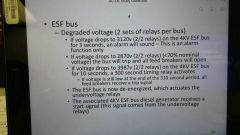
3120V for 3seconds an alarm will sound or... If voltage drops to 2870V the bus will trip and all feed breakers will open or... If voltage drops to 3987V for 10seconds a 300second timing relay activates and if it stays low at the end of the 310 second period all feed breakers receive a trip signal then... The ESF bus is now deenergized which activates the under voltage relays Associated 4kV diesel generator receives a start signal. |
|
|
|
What happens to a 4kV ESF if at anytime during the 310 second period an SI signal actuated? |
All feed breakers receive a trip signal The ESF bus be ones deenergized and that activates the under voltage relays The associated 4kV ESF bus diesel generator receives a start signal (that came from the under voltage relays) |
|
|
|
What time does it take for the diesel to come up to speed and voltage? |
10 seconds |
|
|
|
What is the purpose of load sequencing on a diesel generator |
Sequencing prevents overloading the diesel by starting all the loads at one time |
|
|
|
With a diesel startup when will a containment spray pump start up? |
They will only start if an auto start signal is present and they would start within 15-18seconds (otherwise they will be prevented from starting until the other loads are sequenced on) |
|
|
|
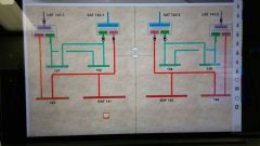
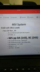
The 4kV loads: ESF (1/2)41 loads |
4kv transformer to bus (1/2)31x CV pp_a SI pp_a RHR_a VC chiller 0A(141) CS pp_a CC pp_a Feeds to CC pp "0" SX pp_a AF pp_a VA supply and exhaust fan 0A(141), 0C(241) non-esf |
|
|
|
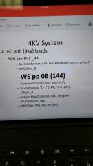
4kv ESF (1/2)42 bus loads: |
4kv transformer to bus _132x CV pp_b SI pp_b RHR_b VC chiller 0B(142) CS pp_b CC pp_b Feeds to CC pp "0" SX pp_b VA supply and exhaust fan 0B (142), 0D(242) non ESF |
|
|
|
Non ESF bus _43 4kv loads |
|
|
|
|
Non ESF _44 for 4kV |
|
|
|
|
What are the trips for the 4kV ESF SAT feed breaker? (_412&_422) |
Manual Degraded voltage after approximately 310 second delay θA and θC or ground Overcurrent actuate the breaker 86 device D/G @ speed and volts with UV on bus |
|
|
|
EDG breaker (_413& _423) results(interlocks) of a manual close: |
No lockouts on reserve feed breaker, EDG breakers, and SAT breakers Diesel at rated speed and voltage Sync switch on Synchrocheck Relay Satisfied (of bus is alive) C/S to close |
|
|
|
EDG breaker closed automatic system interlocks: |
SAT breaker: no lockouts, open Reserve feed breaker: no lockouts, open EDG breaker: No lockouts ESF to non ESF breaker: open Diesel @ rates speed and volts UV condition on bus C/S "after trip" or surveillance test switch in "test" and breaker control switch in any position other than PTL. |
|
|
|
EDG breaker trip system interlocks |
Test start: manual, any EDG trip Under voltage start: 1)overspeed 2) emergency stop pushbutton 3) differential current 4) phase or ground Overcurrent 5)reverse power 6) Under frequency 7)Loss of field 8)SAT breaker Lockout Safety Injection start: differential current, emergency stop pushbutton is always available |
|
|
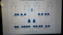
Know this picture |
|
|
|
|
480 V system ESF Buses |
Still subject to sepration requirements and it is the normal power supply to the plants 120 VAC instrument buses via instrument inverters |
|
|
|
The 120 VAC buses and inverter purpose? |
Supplies reliable source of regulated instrument and control power for: reactor protection system(RPS), ESF system control and indication and Process I&C systems. |
|
|
|
How many I&C buses are supplies by the 480 V ESF? |
Two And each bus can receive power from the inverter or constant voltage transformer. |
|
|
|
What causes the Security Diesel Generator to start and what does it feed? |
It auto starts on a low voltage on bus and it supplies power to: Plant radio power supply U1 and U2 RM-11 normal power supply Security lighting power supply Telephone system power supply Security computer power supply |
|
|
|
AC distribution supplies all plant what's? |
Valve motor power Pump power (except 1B AF pump) Control and isolation Reactor protection power |
|
|
|
What does the 125VDC supply?(general) |
Supplies control power to operate breakers remotely and provide protective tripping. |
|
|
|
The 125 VDC for each ESF division supplies control power to? |
Reactor trip switchgear Main control board ESF section ESF switchgear control systems Other safety related systems requiring DC power In control board ESF section |
|
|
|
What is the safety design basis for the 125VDC besides redundant and separated? |
Loss of either system will not prevent safe shutdown during a DBA LOCA concurrent with loss of all off-site power. |
|
|
|
125VDC is supplied by? |
It is supplied by: Normal Battery Charger Emergency Battery and Backup opposite unit 125VDC bus It also supplies nonESF 125VDC bus by two fuses in series separate ESF/non-ESF buses. |
|
|
|
Normal 125VDC /reserve feed ensures control power is available to? |
Main Generator relating and metering MCR turbine panel ESF and non ESF buses (480V, 4160V & 6900V) It consists of normal and reserve feed breakers at 125. |
|
|
|
What will the loss of any 125VDC buses result in? |
A reactor trip |
|
|
|
Purpose of the 250VDC is to supply power to what loads? |
Computer inverter Main turbine emergency oil pump Generator air side seal oil backup pump B&C Feedwater pump emergency oil pumps Main condenser vacuum breaker |
|
|
|
What are the three 250 VDC distribution center types |
Normal-Battery charger Emergency-Battery Backup- opposite unit 250VDC bus |
|