![]()
![]()
![]()
Use LEFT and RIGHT arrow keys to navigate between flashcards;
Use UP and DOWN arrow keys to flip the card;
H to show hint;
A reads text to speech;
100 Cards in this Set
- Front
- Back
|
Minimum taxiway width for 180° turn? |
A319 = 68' A320 = 75' Should not attempt on 75', but 100' is comfortable. |
|
|
Describe relationship of nose, wingtips & tail during a turn |
Wingtip swings largest arc (min obstruction limit) Tail next Nose smallest |
|
|
Location of all cabin entrance doors
(can they be opened from the exterior) |
A320 and A319: 4 cabin entrance doors -- 2 on each side ofthe aircraft. 1L, 1R, 2L, & 2R They can be opened from the exterior. |
|
|
COCKPIT DOOR selector switch momentarily moved to LOCK: causes what to happen |
All normal means of door operation from the cabin are inhibited for 15 minutes. |
|
|
Describe Door/Oxy Page for all exterior doors and emergency exits |
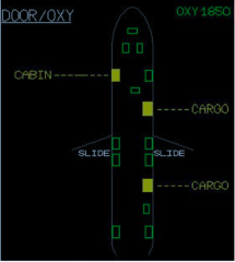
Cabin Cargo Avionics Overwing (Amber: cover removed or door open) Green - closed/locked Amber- unlocked |
|
|
Recall the flight deck indication when slides are armed |
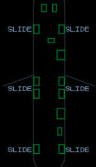
The word SLIDE is present in white on the DOOR/OXY page |
|
|
Recall the emergency equipment stored on the flight deck |
- 4 crew life vests (orange) - 1 halon fire extinguisher - 1 crash ax - 4 crew oxygen masks - 2 escape ropes - 1 Protective Breathing Equipment (PBE) |
|
|
How many portable oxygen bottles? |
5 |
|

Explain the controls and indicators on the overhead OXYGEN panel.
|
MASK MAN ON pb: -- AUTO – a signal is automatically sent to open thepassenger mask doors when the cabin altitude exceeds 14,000 feet. -- Selected – manually sends a signal to deploy masks.
PASSENGER SYS ON light – illuminates white when either an automatic or manual signal has been sent to deploy the passenger masks.
CREW SUPPLY pb – controls the crew oxygen low pressure supply valve: -- ON (lights out) – the supply valve is open, and low pressure oxygen is supplied to the masks.
-- OFF (white) – the supply valve is closed. |
|
|
Recall the oxygen indications on the DOOR/OXY page. |

OXY – senses high pressure oxygen and the indication turnsamber if: -- there is insufficient bottle pressure, or -- the CREW SUPPLY pb has been selected OFF. REGUL LO PR – senses low pressure oxygen and appears if inadequate pressure is beingdelivered to the crew oxygen masks. |
|
|
Recall the functions of the three positions of theEMER EXIT LT switch. |

OFF – the emergency lighting is selected OFF. ARM – the emergency lights will activate automatically with the loss of their normal electrical power sources. ON – the emergency lighting illuminates. |
|
|
Lighting still available in the flight deck while in the emergency electricalconfiguration or on battery power alone. |
1. CA’s flood lights. 2. FO’s dome light. 3. STBY COMPASS light. Lights must be selected on |
|
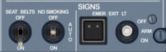
Describe the functions of the 3-position NOSMOKING switch in the AUTO position. |
-- NO SMOKING signs are illuminated. -- EXIT signs illuminate when the landing gear is extended. -- EXIT signs extinguish when the landing gear is retracted. |
|
|
Describe the functions of the X BLEED knob located on the overheadAIR COND panel. |
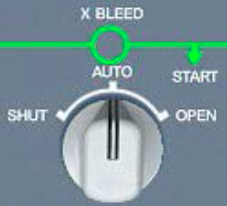
SHUT – manually closes the crossbleed valve, overriding the autologic of the Bleed Monitoring Computers (BMCs).
AUTO – the BMCs automatically control the opening and closing of the crossbleed valve: • The crossbleed valve opens automatically if the APU bleed valve is opened. • The crossbleed valve closes automatically if the APU bleed valve is closed, or if a bleed leak is detected
OPEN – manually opens the crossbleed valve, overriding the auto logic of the BMCs. |
|
|
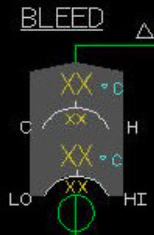
Recall what the green GND symbol represents on the BLEED page |
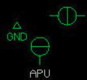
The green GND symbol appears whenever the aircraft is on the ground |
|
|
Recall the indications when external high pressure air is connected tothe aircraft |
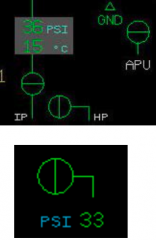
Pressure values can be viewed by referencing:• -- Indications on the BLEED page. -- Next to the start valve indications on the ENGINE page. |
|
|
Describe how the engine bleed valves, the HP valves, and the IP designators are presentedon the BLEED page |
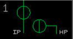
-- The engine bleed valves are presented near the bottom of theBLEED page, without an alphabetical label. -- The HP valves are presented near the bottom of the BLEEDpage and given an HP designator. -- The IP valves are only presented as an IP designator but no valve symbol. The IPdesignator represents the relative location of the IP check valves. |
|
|
Recall when the APU bleed valve appears on the BLEED page |
When the APU MASTER SW pb has beenselected ON |
|
|
Recall the indications when APU bleed air is in use |
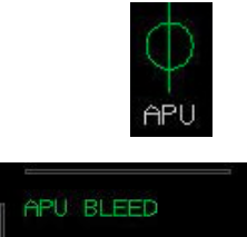
-- APU bleed valve indicates open on the BLEED page. -- APU BLEED is presented in green in the memo section of the E/WD. NOTE: It is not possible to determine whether APU bleed air is inuse solely by referencing the APU BLEED pb on the overhead panel. |
|
|
What areas of the aircraft that are equipped for bleed air leak detection? |
1. Wings for wing anti-ice (dual-loop protection). 2. Engine pylons for engine bleed air (single loop). 3. Fuselage for APU bleed air (single loop). |
|
|
Describe the functions of the Zone Regulator |
- Monitoring and controlling the air conditioning system. --- Compares actual cockpit/cabin zone temperature to temperatures selected on AIR COND panel.
--- Directs Pack Regulators to deliver requested cold air to the mixing unit. --- Uses trim air valves to add hot air to the zones to meet temperature requests.
Providing air conditioning system information to the SD (Lower ECAM). |
|
|
Recall the COND page indications of a Zone Regulator failure. |
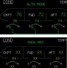
If the primary channel fails, ALTN MODE appears ingreen at the top of the COND page.
If the primary AND secondary channels fail (totalZone Regulator failure), PACK REG appears in greenat the top of the COND page, and all temperaturevalues and trim air valve indications are replaced withamber Xs. |
|
|
Explain the function of the two Pack Regulators. |
-- Automatically controlling and monitoring each pack and regulating cold air output inaccordance with the demands required by the Zone Regulator. -- Providing pack information to the SD (Lower ECAM) |
|
|
Recall the indications of a Pack Regulator failure |
-- If a primary channel fails: ---- all pack information presented on the BLEED page is still present, and ---- an ECAM failure message appears in the E/WD memo section. -- If the primary AND secondary channels fail (total Pack Regulator failure): ---- indications for the corresponding pack will be replaced with amber Xs, and ---- an ECAM failure message appears in the E/WD memo section. |
|
|
which cargo compartment directly receives heating andventilation to support the transport of live animals. |
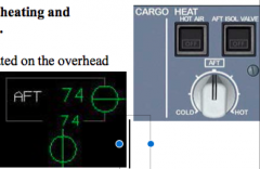
The aft compartment, using the controls located on the overhead CARGO HEAT panel. Status of the aft cargo heat system can be monitored by referencing the COND or CRUISE pages. |
|
|
Recall how many pressurization controllers are installed on the aircraft for automaticallycontrolling pressurization. |
There are two pressurization controllers installed; however, only one is active at a time.
The active controller can be viewed on the CAB PRESS page as a SYS 1 or SYS 2 labeled in green. |
|
|
Describe three ways for the active and standby pressurization controllers to transfer roles |
Automatic: 1. The active and standby controllers transfer roles shortly after landing. 2. The standby controller will become active in the event the active controller fails. Manual: 3. The standby and active controllers can be transferred manually by placing the MODESEL pb to MAN for 10 seconds, and then returning it back to the AUTO (lights out)mode. |
|
|
Describe the function of the LDG ELEV selector on the overhead CABIN PRESS panel |
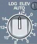
In AUTO, the FMGCs provide the landing field elevation so that the pressurization controllerscan construct an optimized pressure schedule. Outside of the AUTO detent, the landing field elevation is set manually byreferencing the scale around the selector. This is performed if: • the FMGCs are inoperative, or • the airport of intended landing is not in the FMS database. |
|
|
Describe the manual pressurization controls on the overheadCABIN PRESS panel. |
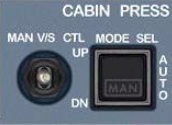
MODE SEL pb – selecting to MAN enables manual controlof the outflow valve. MAN V/S CTL toggle switch – manually controls theoutflow valve: o UP opens the outflow valve (raising the cabin altitude). o DOWN closes the outflow valve (lowering the cabin altitude). Monitor the pressurization performance on either the CAB PRESS or CRUISE pages. |
|
|
Describe what action the crew must take with the pressurization system if the flight mustreturn to the departure airport. |
Below a predetermined altitude, no action is required. The pressurization system’s ABORTMODE automatically returns the cabin altitude to the departure airport elevation. |
|
|
Describe the function of the DITCHING pb on the overhead CABIN PRESS panel. |
Placing the DITCHING pb to ON causes openings below the flotation line to close. Openingsinclude the: • outflow valve (if the MODE SEL pb is AUTO) • emergency ram air inlet (if open) • avionics ventilation inlet valve • avionics ventilation extract valve • pack flow control valves |
|
|
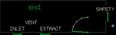
Describe the Open configuration of theavionics ventilation system. |
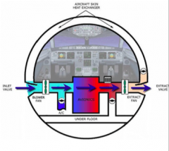
-- Used if warm ambient conditionsexist while the aircraft is on theground. -- Outside air is drawn through theopen inlet valve by the blower fan where it then passes around the avionics equipment. -- The extract fan then pulls the heatedair and expels it out through thefully open extract valve. -- Avionics compartment air does notpass through the aircraft skin heatexchanger or the cargo under floor. |
|
|
Describe the Closed configuration of theavionics ventilation system. |
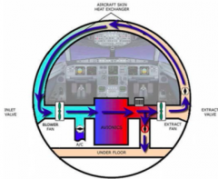
-- Used during flight or during cold ambient conditions on the ground. -- Avionics compartment air iscooled via an aircraft skin heat exchanger and circulated by theblower and extract fans. -- The inlet and extract valvesremain closed. -- Air is expelled through the cargo under floor and out through the outflow valve. |
|
|
Describe the Intermediate configuration of the avionics ventilation system. |
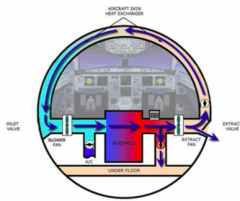
-- Used if warm ambient conditionsexist during flight (airborne orthrust levers placed to a takeoffposition while on the ground).
-- Same as the closed configuration, except that a small internal flap within the extract valve opens to expel some of the heated avionics compartment air overboard. |
|
|
Describe the Smoke configuration ofthe avionics ventilation system |
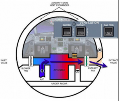
-- Used in response to the Avionics Equipment Ventilation Computer (AEVC) sensing smoke in the avionics compartment. -- The BLOWER and EXTRACTpbs are placed to the OVRD (override) position inaccordance with ECAM procedure. -- This closes the inlet valve, stops the blower fan, and isolates the cargo under floor and aircraft skin heat exchanger. -- Conditioned air is provided by the air conditioning system through an air conditioning inlet valve. -- The extract fan draws the conditioned air through the avionics compartment, and expels it through the small internal flap within the closed extract valve. |
|
|
Which areas of the wings and engines receive ice protection? |

-- Wings – outboard three slats (Slats 3, 4, and 5). -- Engines – engine nacelle leading edge. |
|
|
Recall the conditions that require the use of wing anti-ice. |
-- Turn on wing anti-ice whenever there is an indication the airframe is accumulating ice. -- Indications may be observed on the visual ice indicator between the windshields or on the wipers. |
|
|
Recall the conditions that require the use of engine anti-ice. |
-- Engine anti-ice should be used whenever icing conditions exist or are anticipated forboth ground and flight operations. -- Engine icing conditions exist when the OAT is 10o C or below, and visible moisture inany form is present (clouds, fog with visibility of one mile or less, rain, snow, sleet, andice crystals). |
|
|
Recall whether engine bleed air must be selected ON before using engine anti-ice |
No. Engine anti-ice is plumbed independently off of the high pressure compressor; therefore,engine bleed air does NOT have to be selected ON to use engine anti-ice |
|
|
Describe the indications when engine anti-ice is selected on |
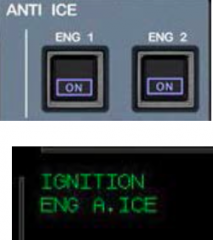
--A blue “ON” light illuminates on the respective pb. -- The memo section of the E/WD displays ENG A.ICE in green. -- Continuous ignition is automatically activated for that respective engine – IGNITION displays in the E/WD memo section. -- The N1 limit for that engine is automatically reduced. -- Increase in engine idle speed. |
|
|
Describe the indications when wing anti-ice is selected on. |
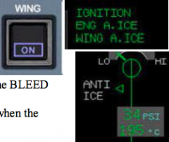
-- A blue ON light illuminates on the WING pb. -- The memo section of the E/WD displays WING A.ICE in green. -- The words ANTI ICE appear in white on each side of the BLEEDpage. -- Green arrows appear on each side of the BLEED page when therespective wing anti-ice valves open for each wing. |
|
|
Recall the caution regarding use of wing anti-ice with slats extended |
Extended flight in icing conditions should be avoided due to reduced wing anti-ice capability withthe slats extended. |
|
|
Describe what causes the amber FAULT lights to illuminate on the WING and ENG 1(2)ANTI ICE pbs. |
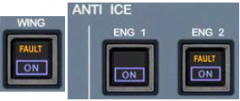
-- Momentarily during valve transit. -- Disagreement between the selected position and the actual position of the valve. -- For the WING pb, if low bleed air pressure is detected. |
|
|
Describe how the two Window Heat Computers (WHCs) and the three ProbeHeat Computers (PHCs) automatically provide window and probe heat whenthe PROBE/WINDOW HEAT pb is in the AUTO (lights out) position. |

-- With at least one engine running on the ground, all six windows, the pitottubes, static ports, and AOA vanes are automatically heated electrically at low level. -- The TAT probes are not heated on the ground. -- While in flight, the two forward windshields, the pitot tubes, static ports, TAT probes, and AOA probes transition to normal heating levels. -- There is only one heat level for the four side windows. |
|
|
Explain the function of the PROBE/WINDOW HEAT pb when selected ON |

-- On the ground, low-level heat will be applied to the windows and probes prior to engine start.
-- After start of the first engine, the system reverts to its programmed logic, but the ON light in the pb remains illuminated, unless manually selected back to AUTO (lights out).
-- In flight, there is no difference in system performance or logic compared with the pb inAUTO. |
|
|
Explain how the Flight Management Guidance Computers (FMGCs) provide commands forthe autopilots, flight directors, and autothrust during normal operations. |
-- FMGC1 generates commands for: • Autopilot 1. • Captain’s Flight Director. • Autothrust, if no autopilot is selected or Autopilot 1 is selected. -- FMGC2 generates commands for: • Autopilot 2. • First Officer’s Flight Director. • Autothrust, if Autopilot 2 is selected. |
|
|
Recall what computations the Flight Augmentation Computers (FACs) provide to theautoflight system. |
The FACs provide flight envelope calculations to the autoflight system to ensure limits are notexceeded, such as: • Maximum and minimum airspeeds • Maneuvering speeds • Configuration limits • Alpha (angle of attack) limits. |
|
|
Recall the function of the Flight Mode Annunciator (FMA), located at the top of thePrimary Flight Display (PFD). |
1. The primary tool to monitor the status and performance of the autoflight systems. 2. Monitor the approach capabilities of the aircraft. |
|
|
Recall the organization of the Flight Mode Annunciator (FMA). |

The FMA is divided into five columns: • Column 1: autothrust system indications. • Column 2: autoflight vertical mode indications. • Column 3: autoflight lateral mode indications. • Column 4: approach capabilities and minimums. • Column 5: autoflight status. |
|
|
Explain the meaning of the various colors presented on the FMA |
Green – engaged modes. Blue – armed modes or numbers. Magenta – altitude constraints (if vertical path includes a level segment). White – approach capabilities, certain autothrust modes, and autoflight system status. Amber – thrust and/or flight control system caution messages. Red – significant flight control system degradation. |
|
|
Recall how to engage and disengage the autopilot. |
Engagement – selecting either the AP1 or AP2 pbs located on the Flight Control Unit (FCU). Disengagement: • Selecting the autopilot disconnect pb on either sidestick (preferred method). • Selecting the illuminated AP1or AP2 pb on the FCU. • Displacing either sidestick or displacing the rudder pedals. |
|
|
Recall the various autopilot indications presented within Column 5 of the FMA. |
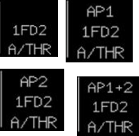
-- With no autopilot engaged, the top line will be blank. --If the AP1 pb is selected on the FCU, AP1 will bedisplayed. --If the AP2 pb is selected, AP2 will be displayed. --If both AP pbs are selected during an ILS approach, AP1+2 will be displayed. |
|
|
Recall how to engage and disengage the flight directors. |
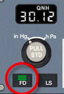
-- Automatically engaged when electrical power is established on the aircraft while on the ground.
-- Engaged or disengaged by selecting the FD pbs located on each Electronic Flight Instrument System (EFIS) control panel. |
|
|
Recall the flight director indications presented within Column 5 of the FMA |
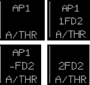
- If both flight directors are disengaged, the second line willbe blank. - If both flight directors are engaged, 1FD2 will be displayed. - If the CA’s flight director is disengaged, but the FO’s is still engaged, -FD2 will be displayed. - If the FO’s flight director is disengaged, but the CA’s is still engaged, 1FD- will be displayed. - If FMGC 1 has failed, 2FD2 will be displayed. - If FMGC 2 has failed, 1FD1 will be displayed. |
|
|
Describe three different types of autothrust status and the indications on the FMA. |
OFF – Thrust must be controlled manually using the thrust levers. • FMA Column 1 and the bottom row of Column 5 will be blank. ARMED – Thrust output corresponds to the position of the thrust levers. • The autothrust system automatically arms if the flight directors are on and: o the thrust levers are placed to either the TOGA stop or the FLX detent duringtakeoff. o during flight, the aircraft is configured in FLAPS 1 or greater, and the thrustlevers are placed to the TOGA stop. • FMA Column 1 will display a manual thrust setting (e.g. MAN TOGA, MAN FLX, etc.)and the bottom row of Column 5 will display A/THR in blue. ACTIVE – Thrust output varies automatically to meet thrust requirements, but the thrust leversdo not move. • The autothrust system becomes active automatically if the system was previously armed,and the thrust levers are placed into the active autothrust range: o Just above IDLE stop, up to and including the CLB detent for normaloperations, or o Just above the IDLE stop, up to and including the MCT detent for single-engineoperations. -- The autothrust system may be manually selected on, using the A/THR pb on the FCUand will engage if the thrust levers are in the active autothrust range, as described above. -- FMA Column 1 will display the appropriate autothrust mode, and the bottom row ofColumn 5 will display A/THR in white. |
|
|
Recall how to engage and disengage the autothrust system. |
Engagement: -- Normally, the autothrust system is armed on takeoff when the thrust levers are moved totakeoff power (FLX or TOGA) and engaged when the pilot moves the thrust levers to theCLB detent at thrust reduction altitude. -- If not already engaged, the autothrust system may be engaged by first selecting theA/THR pb located on the FCU and then placing the thrust levers into the CLB detent. Disengagement: -- Normally, the autothrust system is disengaged on landing when the thrust levers areretarded to the IDLE stop. -- Move the thrust levers to match current thrust output by referencing the N1 indicationson the E/WD. Then select one of the autothrust instinctive disconnect pbs located on thethrust levers (preferred method, except during landing). -- Select the illuminated A/THR pb while the autothrust system is active. The autothrustsystem reacts the same as if there were an autothrust system failure – thrust will “lock”at its current setting until the pilot moves the thrust levers -- Pressing the autothrust instinctive disconnect pb on the thrust levers. Engine thrust willsurge to match the position of the thrust levers (indicated by white circles on N1 gauges). |
|
|
Explain the two modes of the autothrust system. |
Fixed Thrust: • Constant thrust output is used, and airspeed is controlled through pitch. • Used most often during climbs and descents when no specific rate is required. Variable Thrust: • Thrust output varies to maintain airspeed. • Used most often during level flight, or during climbs and descents when a specific rate must be maintained. |
|
|
Recall the indications of the fixed and variable modes ofthrust. |
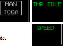
Fixed - anything other than SPEED or MACH (e.g. THRCLB, THR IDLE, MAN TOGA, etc.). Variable – either SPEED or MACH, depending on aircraft altitude. |
|
|
Recall the default mode of an engaged autothrust system with all flight guidance disengaged(i.e. no autopilot and flight directors). |
SPEED or MACH |
|
|
Explain the function of Alpha Floor in the autothrust system. |
-- Automatically commands TOGA thrust if certain angle of attack limits are exceeded. -- Functions regardless of thrust lever position and autothrust engagement, assuming autothrust is operational (not MEL’d out) and flight control system is in Normal Law. -- Available from liftoff to 100 ft radio altitude on approach. -- Once the condition causing Alpha Floor is resolved, thrust remains at TOGA (TOGA LK) until pilot intervention. |
|
|
Know the indications associated with Alpha Floor. |
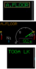
- A. FLOOR in green surrounded by an amber box in Column 1 of the FMA. - A. FLOOR appears in amber above the N1 indications on the E/WD. - Engine thrust automatically accelerates to TOGA. - Once condition causing Alpha Floor no longer exists,TOGA Lock engages and TOGA LK replaces the A. FLOOR indication |
|
|
Describe SELECTED guidance in the autoflight system |
SELECTED guidance is the result of the pilot selecting actions on the FCU. SELECTED functions are performed by momentarily pulling any of the four spring loaded knobs located on the FCU and setting the desired value: o Pulling the SPD/MACH knob allows the pilot to select a specific speed. o Pulling the HDG/TRK knob allows the pilot to select a specific heading. o Pulling the altitude knob allows the pilot to perform an open climb or descent. o Pulling the V/S / FPA knob allows the pilot to select a specific vertical speed or flight path angle climb or descent. SELECTED guidance always takes priority over MANAGED guidance. |
|
|
Describe MANAGED guidance in the autoflight system. |
-- Allows the autoflight system to follow optimized airspeeds computed by the FMGCs. -- Allows the autoflight system to follow the lateral and vertical profiles defined by the FMGCs’ entered flight plan. -- Functions are performed by momentarily pushing the knobs located on the FCU: o If a SELECTED speed is in use, a MANAGED speed may be activated bypushing the SPD/MACH knob. o If a heading is being flown, MANAGED navigation may be armed or activatedby pushing the HDG/TRK knob (provided the aircraft is currently on, near, orintercepting the flight plan route). o A MANAGED climb or descent can be performed by pushing the altitude knob(provided MANAGED navigation is in use). o Pushing the V/S / FPA knob does not result in activating a MANAGED mode.This action simply commands the autoflight system to level the aircraft (V/S 0). |
|
|
Recall how changes within the FMA are highlighted. |

A white box momentarily appears around the indication that has changed. |
|
|
Recall the function of the Speed Reference System (SRS) in Column 2 ofthe FMA during takeoff and go-around. |

Provides vertical guidance so the aircraft maintains: • V2+10 kts with both engines running. • V2 or current airspeed (whichever is higher) if single-engine. |
|
|
Recall when SRS becomes active in Column 2 of the FMA. |
-- V2 (Vapp for go-around) is entered in the MCDU. -- FLAPS 1 or greater is selected. -- The flight directors are on. -- Takeoff or go-around thrust is applied. |
|
|
Recall what occurs when the FCU Altitude Knob is pulled during flight. |
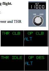
If the selected FCU altitude is above the current aircraft altitude: • OP CLB appears in green in Column 2 of the FMA. • If autothrust is engaged, thrust will increase to climb power and THR CLB appears in Column 1 of the FMA. • Flight plan altitude constraints will be ignored. If the selected FCU altitude is below the current aircraftaltitude: -- OP DES appears in green in Column 2 of the FMA. -- If autothrust is engaged, thrust will reduce to idle power and THR IDLE appears in Column 1 of the FMA. -- Flight plan altitude constraints will be ignored. |
|
|
Recall what occurs when the FCU Altitude Knob is pushed during flight inMANAGED navigation (green NAV in Column 3 of the FMA). |
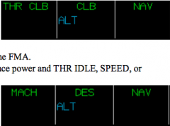
If the selected FCU altitude is above the current aircraft altitude: • CLB appears in green in Column 2 of the FMA. • If autothrust is engaged, thrust will increase to climb power and THR CLB appears in Column 1 of the FMA. • Reasonable flight plan altitude constraints will be honored. If the selected FCU altitude is below thecurrent aircraft altitude: • DES appears in green in Column 2 of the FMA. • If autothrust is engaged, thrust will reduce power and THR IDLE, SPEED, or MACH will appear in Column 1 of the FMA. • Reasonable flight plan altitude constraints will be honored. NOTE: MANAGED vertical performance (CLB or DES) requires MANAGED navigation(NAV). |
|
|
Recall the function of the FCU Vertical Speed Knob. |
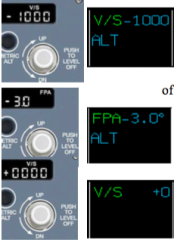
Pulled: -- Commands a climb or descent at the selectedvertical speed or flight path angle. -- V/S ±XXXX or FPA ± X.X appears in Column 2 ofthe FMA with the selected vertical speed or flightpath angle. -- Flight plan altitude constraints will be ignored. Pushed – commands a vertical speed of zero and aircraft levels off. |
|
|
Recall the indications for altitude hold in Column 2 of the FMA |
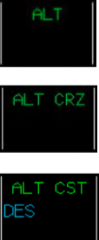
ALT - Green – hold mode engaged. - Blue – hold mode armed. - Magenta – hold mode armed for a flight plan altitude constraint. ALT CRZ • Green – hold mode engaged at the programmed cruise altitude. ALT CST • Green – hold mode engaged at a flight plan altitude constraint. |
|
|
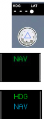
Recall the approach mode indications in Column 2 of the FMA. |
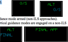
G/S • Green – glide slope mode engaged. • Blue – glide slope mode armed. FINAL • Blue – final approach vertical guidance mode armed (non-ILS approaches). NOTE: when both lateral and vertical guidance modes are engaged on a non-ILSapproach, Columns 2 and 3of the FMA combine todisplay FINAL APP. |
|
|
Explain the meaning of the RWY and RWY TRK indications in Column 3 of the FMA |

RWY - Green – Runway mode engaged. - Provides lateral guidance during takeoff roll and initial climb when a localizer is available on the takeoff runway. - Replaced by RWY TRK or NAV soon after takeoff. RWY TRK - Green – Runway Track mode engaged. - Provides lateral guidance after takeoff based on extended takeoff runway centerline. - Does not require a localizer signal. - Engages automatically if NAV is not armed for takeoff. |
|
|
Recall what occurs when the FCU HDG/TRK Knob is pulled during flight. |
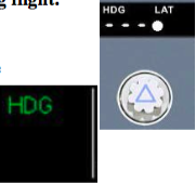
- HDG or TRK appears in green in Column 3 of the FMA - The pilot can select aircraft heading or track by turning the HDG/TRK Knob. |
|
|
Recall what occurs when the FCU HDG/TRK Knob is pushed during flight |
If the aircraft is on or near the flight plan course: • NAV appears in green in Column 3 of the FMA. • Managed navigation provides lateral guidance along the flight plan course. If the aircraft is not on or near the flight plan course: • NAV appears in blue in Column 3 of the FMA. • Managed navigation is armed. • Once the flight plan course is intercepted, the numbers in the FCU HDG/TRK window will be replaced with 3 dashes. |
|
|
Recall the approach mode indications in Column 3 of the FMA |
LOC – provides localizer lateral guidance when the LOC or APPR pbshave been armed and the ILS frequency is tuned. • Green – localizer mode engaged. • Blue – localizer mode armed.
APP NAV
Green – final approach lateral guidance modeengaged (non-ILS approaches).
Blue – final approach lateral guidance mode armed (non-ILS approaches).
NOTE: when both lateral and vertical guidance modes are engaged on a non-ILSapproach, Columns 2 and 3 of the FMA combine to display FINAL APP. |
|
|
Explain the meaning of the GA TRK indication in Column 3 of the FMA |

Green – Go-Around Track mode engaged.
Guides the aircraft along the existing aircraft ground track at the time of engagement.
NOTE: If the aircraft was previously in the ILS, NAV, APP NAV, or FINAL APP modes, Column 3 will automatically revert to NAV during the go-around with flaps1 or greater. |
|
|
Recall what a “*” (star) represents when presented in the FMA? |

A capture (acquire) mode is engaged. • ALT*: altitude capture mode is engaged. • ALT CST*: altitude capture mode is engaged due to an altitude constraint. • G/S*: glide slope capture mode is engaged. • LOC*: localizer capture mode is engaged. |
|
|
Recall the default modes of Columns 2 and 3 of the FMA when flight guidance (autopilotand/or flight director) is engaged after being off. |

Column 2 will default to the aircraft’s current verticalspeed at the time of engagement (e.g. V/S +0 or V/S -900). Column 3 will default to HDG. |
|
|
Describe the flight interphone system |
-- Allows communications within the flight deck and between the flight deck and theFLT INT jack on the external power panel (pushback coordinator). -- Use the INT/MECH transmission key on the Audio Control Panels (ACPs). |
|
|
Describe the cabin interphone system |
-- Allows communications between the flight deck and the cabin (flight attendants). -- Use the CAB/ATT transmission key on the ACPs. |
|
|
Describe the service interphone system |
-- Allows communications between the flight deck and maintenance receptacleslocated around the exterior of the aircraft. -- Use the CAB/ATT transmission key on the ACPs. |
|
|
How do you make voice transmissions |
1. by pulling the sidestick triggeraft, 2. pushing the hand microphone push-to-talk pb, 3. pressing and holding the INT/RAD switchon the ACP to the RAD position. |
|
|
Recall the purpose of the Radio Management Panels (RMPs). |
Allows tuning of communication radios and standby tuning of navigation radios. |
|
|
Recall the purpose of the Audio Control Panels (ACPs). |
1. Allows selection of a communications radio for transmitting and receiving. 2. Controls volume for received transmissions. 3. Allows transmission on the Public Address system. 4. Allows filtering of Morse code signals from NAVAID reception. |
|

Recall the purpose of the INT/RAD switch on the ACPs. |
INT – allows hands-free (hot mic) transmission on the flight interphone using the boom mic or oxygen mask.
Neutral – the boom mics and oxygen masks are disconnected from transmitting on the flight interphone system unless the pilot actuates the trigger on the sidestick or the RAD switch. Flight interphone reception is unaffected.
RAD – when pressed and held, the pilot transmits on the selected communications radio. |
|
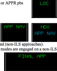
Recall the function of the AUDIO SWITCHING control knob on theoverhead panel. |
Allows replacement of a failed CA’s or FO’s ACP by moving the knobto either CAPT 3 or F/O 3. A green “AUDIO 3 XFRD” message will then display in the memosection of the E/WD. |
|
|
Describe the indications associated with an incoming SELCAL |

CALL flashes in amber within the respective communication radio transmission keys (VHF 1/2/3 or HF 1/2).
Buzzer sounds. |
|
|
Describe the indications associated with an incoming Ground Call |

MECH flashes in amber within the INT transmission keys. Buzzer sounds. |
|
|
Describe the indications associated with an incoming Cabin Call |

ATT flashes in amber within the CAB transmission keys.
Buzzer sounds. |
|
|
How do you extinguish the flashing call light |
Pressing the RESET key on the ACP will extinguish a flashingCALL, MECH, or ATT light in those keys. |
|
|
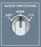
Recall how to enable/disable the mask microphone within the flight deck oxygen mask. |
The oxygen mask microphone is enabled as soon as the left door,which covers the mask, is opened. The white OXY ON flagindicates that the microphone is enabled. The oxygen mask microphone may be disabled by closing the leftdoor, and then selecting the PRESS TO TEST AND RESET pb onthe oxygen stowage box controls. NOTE: The microphone installed for the 4th occupant oxygen maskis not operational. |
|
|
Describe the two methods to make a PA announcement. |
1. Using the PA handset mounted on the pedestal. 2. Pressing and holding the PA transmission key located on the ACPs, and speaking into the headset boom microphone or oxygen mask. |
|

Explain the Calls Panel control: ATTND ADV pb |
NOT used incompany procedures. |
|

Explain the Calls Panel control: MECH pb |
-- COCKPIT CALL light illuminates on the external power panel. -- External horn sounds. |
|
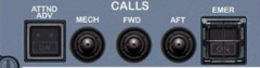
Explain the Calls Panel control: FWD pb |
High/low chime sounds throughout the cabin.
Steady pink light illuminates on the forward area call panel.
CALL CAPTAIN message and a steady red light appear on the forward attendant indication panel. |
|

Explain the Calls Panel control: AFT pb |
High/low chime sounds throughout the cabin.
Steady pink lights illuminate on the mid and aft area call panels.
CALL CAPTAIN messages and steady red lights appear on the two aft attendant indication panels. |
|

Explain the Calls Panel control: EMER pb
|
ON in white, and CALL in amber flash within the pb.
Pink lights flash on all area call panels.
High/low chime sounds three times throughout the cabin.
EMERGENCY CALL messages and flashing red lights appear on all attendant indication panels. |
|

Explain the RCDR Panel control: GND CTL |
ON: illuminates blue within the pb, and the Cockpit Voice Recorder (CVR) and Digital Flight Data Recorder (DFDR) are energized. AUTO (lights out): the CVR & DFDR are automatically energized: o after engine start o in flight o for five minutes after electrical power is applied to the aircraft |
|
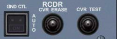
Explain the RCDR Panel control: CVR ERASE |
Erases the tape if the pb is pressed for a short time, the aircraft is on the ground, and the parking brake is on. |
|

Explain the RCDR Panel control: CVR TEST |
Activates the CVR test provided the GND CTL pb is selected ON, and the parking brake is on.
Low frequency tone is heard through the flight deck loudspeakers to indicate a successful test. |